17
Bentone B 30/B 40 J/K
2.2 Acceptance inspection
Make sure everything is delivered and the goods have not been damaged
during transit. If something is wrong with the delivery, report it to the supplier.
Transport damage must be reported to the shipping company.
2.3 Preparations for installation
Check that the burner’s dimensions and capacity range are suitable for the
boiler in question. The power data on the type sign refers to the burner’s min.
and max. power.
2.4 Distribution of oil
In order to achieve good reliability, it is important that the oil distribution
system is designed correctly.
Take the following into account:
- Selection of pipe diameter, pipe length and height difference; see Pump
instruction.
- Pipelines are to be laid with a minimal number of glands.
- The pipes are to be laid so that the oil supply hoses are not subjected to
tensile stresses or are excessively bent when the burner is swung out or
removed for service.
- The ½ “ oil fi lter should be installed so that the fi lter cartridge can easily
be replaced or cleaned. Self-cleaning fi lters are recommended for oils of
a higher viscosity or oils that contain signifi cant impurities.
- Oil-affected parts shall be selected in materials that are capable of
withstanding the medium’s physical properties.
- When installing oil hoses, check that the inlet and return hoses are
fi tted to the appropriate connection on the oil pump. The hoses shall
be located so that they do not bend or become subject to tensile load.
To the suction line on the pump (see paragraph 7.2 pos. 3) should the
supplied oil hose with 90° bend be connected.
- Bleed the oil system. The oil pump/oil preheater may be damaged if run
dry. The vacuum should not fall below 0 bar in the suction line during
start-up.
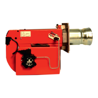
2.4.1 Proposed pipe routing for oil distribution systems
without transport pump
This type of connection should be used only when the oil has a viscosity less than
6mm²/s
1. Oil fi lter
!
Be sure to fi ll the burner
oil system before starting
it for the fi rst time.
1