19
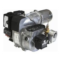
Bentone B 30/B 40 J/K
d
1
d
2
d
3
2.6 Nozzle selection
See under Technical data: Recommended nozzle and nozzle table in order to
select the appropriate nozzle.
2.7 Setting of brake plate and air flow
Prior to commissioning, the basic settings of the burner can be set in
accordance with the diagram. See under Basic settings. Note that it is simply
a matter of a basic setting that should be adjusted retrospectively once the
burner has started. You should then conduct a flue gas analysis and soot
quantity measurement.
2.8 Burner installation
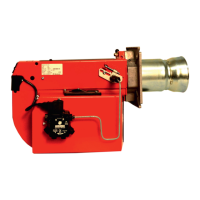
2.8.1 Hole patten
Make sure the hole pattern on the boiler is designed for burner flange.
Combustion
device
d
1
d
2
d
3
B 30 ø 115-150 M8-M12 ø 160-190
B 40 ø 115-175 M10-M12 ø 195-245