24
Bentone B 30/B 40 J/K
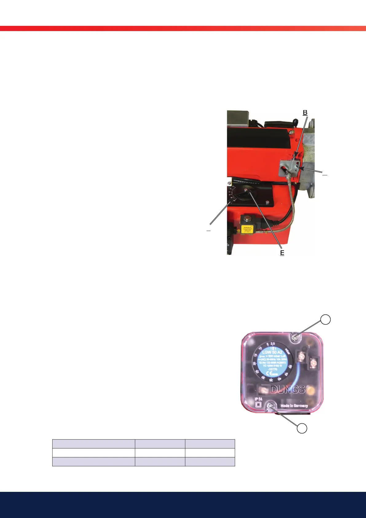
3.8 Nozzle assembly adjustment,
brake plate
The nozzle assembly control is used to achieve the most favourable pressure
drop across the brake plate as possible at the various effect stages. The
nozzle assembly is adjusted manually (B) in order to obtain the optimum
pressure drop for good combustion.
3.9 Air setting
Set the operations switch (S1) on the on position (I). Loosen the
screw (E) that locks the air adjustment knob. Adjust the position
of the air damper using the wheel until the desired air fl ow is
achieved. Clockwise adjustment reduces the amount of air, whilst
an anticlockwise adjustment increases the air fl ow. After adjustment,
lock the damper position using the screw (E). Damper position
can be read on the damper scale (F). Check the air settings by
conducting a fl ue gas analysis..
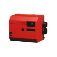
3.10 Setting the air pressure
switch
The air pressure switch should block the burner if the air quantity
supplied for combustion is insuffi cient. The air pressure switch must
be set so that, if there is a defective air supply at the burner’s max.
or min. capacity, it reacts before the monitored pressure falls so
much that it results in poor combustion.
Y
Y
Setting for air pressure switch
1. Remove the protective cover, screw (Y).
2. Start the burner.
3. Carefully turn the scale on the air pressure switch clockwise until the air
pressure switch stops the burner. Is the tolerance on the scale for
the min. air pressure switch approx. ±15%?
4. Try to fi nd the pressure at which the burner stops for both the
minimum and maximum input power by turning the scale. Make a note
of the values and then set the air pressure switch on the basis of the
highest pressure noted at which the burner stopped.
5. The air pressure switch should be set to a pressure approx. 10–15%
lower than the highest noted pressure at which the burner stopped.
6. After setting the air pressure switch, perform repeated starts and run
through the burner’s set output range several times. This is to ensure
the reliable function of the burner. If breakdowns or interruptions occur,
the air pressure switch is probably set to a too narrow position.
7. Fit the protective cover, screw (Y).
Setting area approx.: Type Max. pressure
1-10 mbar LGW 10 A2 500 mbar
2,5-50 mbar LGW 50 500 mbar
B
C
E
F