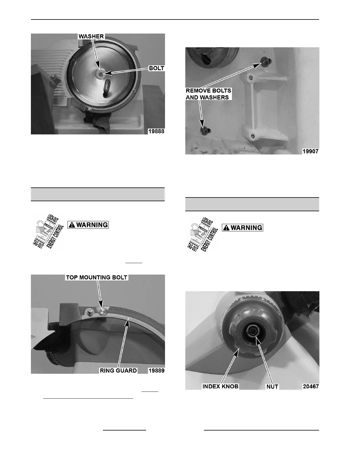
Fig. 26
5. Remove knife.
6. Reverse procedure to install.
7. Torque knife bolt 50 in.-lbs.
8. Check slicer for proper operation.
RING GUARD
Ring Guard Removal
Disconnect the electrical power to
the machine and follow lockout /
tagout procedures.
1. Remove knife as outlined under KNIFE.
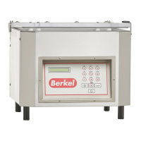
2. Remove top mounting bolt from ring guard.
Fig. 27
3. Remove knife motor as outlined under KNIFE
MOTOR AND MOUNT ASSEMBLY.
NOTE: Knife motor just needs to be moved out of the
way to access bolts and washers.
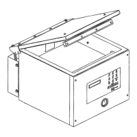
4. Remove bottom two mounting bolts and
washers.
Fig. 28
5. Remove ring guard.
6. Reverse procedure to install.
7. Check slicer for proper operation.
INDEX KNOB
Disconnect the electrical power to
the machine and follow lockout /
tagout procedures.
Removal
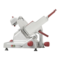
1. Remove index knob cap.
2. Remove nut.
Fig. 29
3. Remove index knob.
Replacement
X13 SLICER - REMOVAL AND REPLACEMENT OF PARTS
F25332 Rev. A (0718) Page 14 of 36