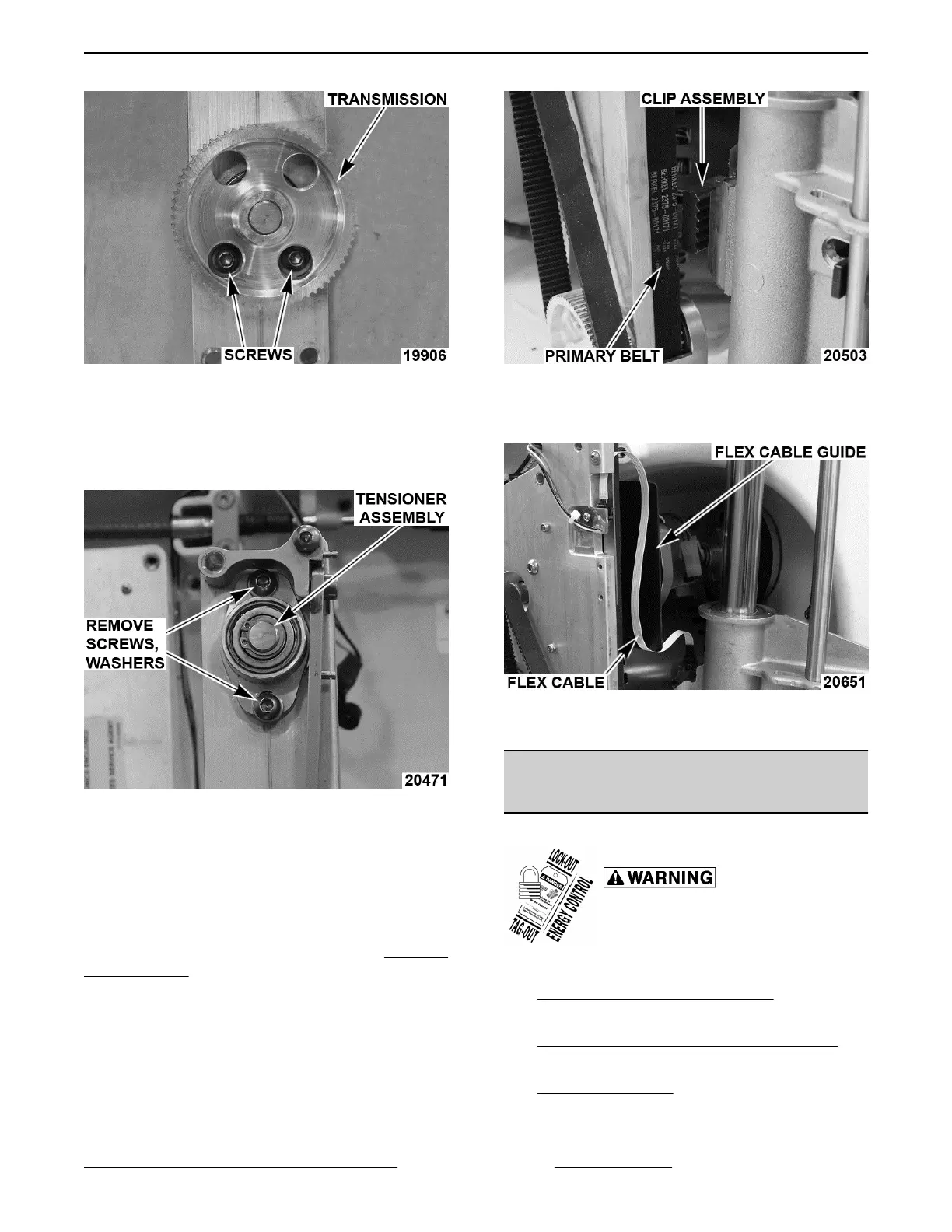
Fig. 37
4. Remove autodrive transmission housing,
primary belt, and transmission.
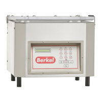
5. Remove screws and washers securing tensioner
assembly.
Fig. 38
6. Remove tensioner assembly.
7. Reverse procedure to assemble.
A. Set primary belt tension by applying hand
pressure to tensioner assembly.
NOTE: If the primary belt was replaced, you will need
to adjust the eccentric pin as outlined under Eccentric
Pin Adjustment .
8. Check slicer for proper operation.
Autodrive Mechanism Installation
1. Reverse removal procedure to install.
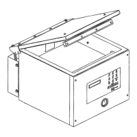
2. Place primary autodrive belt in clip assembly.
Fig. 39
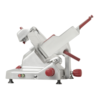
A. Reconnect flex cable last, and make sure
cable is in front of guide assembly.
Fig. 40
3. Check slicer for proper operation.
KNIFE MOTOR AND MOUNT
ASSEMBLY
Motor and Mount Assembly Removal
Disconnect the electrical power to
the machine and follow lockout /
tagout procedures.
1. Remove bottom cover as outlined under
BOTTOM COVER (X13A, X13AE).
2. Remove autodrive assembly as outlined under
AUTODRIVE MECHANISM (X13A, X13AE).
3. Access control board as outlined under
CONTROL BOARD.
A. Remove motor wires from control board.
X13 SLICER - REMOVAL AND REPLACEMENT OF PARTS
Page 17 of 36 F25332 Rev. A (0718)