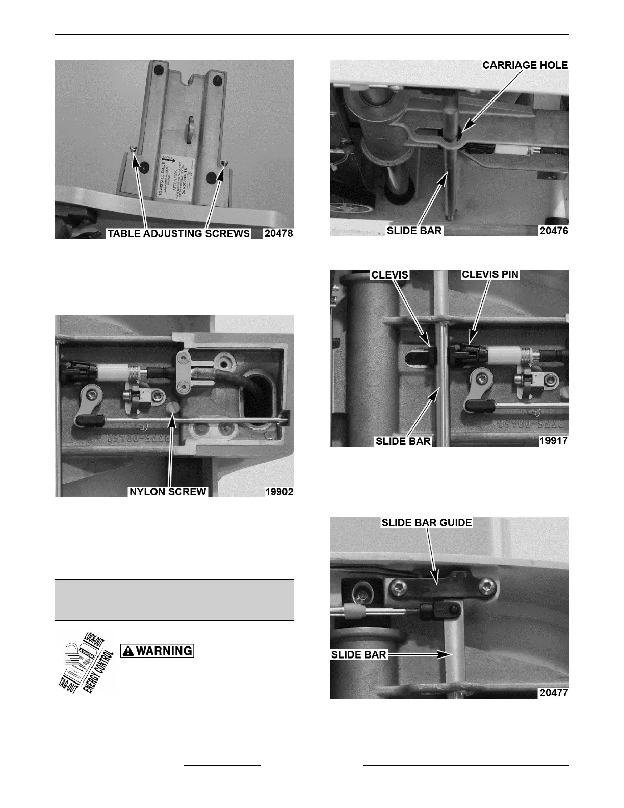
Fig. 59
4. Proper carriage travel.
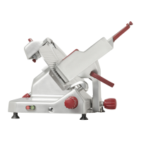
A. Apply Loctite® 2440™ to nylon screw and
adjust to zero clearance with square rail
without binding.
Fig. 60
B. Stand slicer up and ensure carriage moves
freely.
1) Adjust nylon screw if travel is sloppy or
binding occurs.
INTERLOCK CABLES / SUPPORT
ARM ADJUSTMENT
Disconnect the electrical power to
the machine and follow lockout /
tagout procedures.
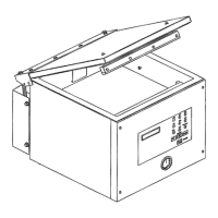
NOTE: With product table installed, slide bar should
be centered in carriage hole.
Fig. 61
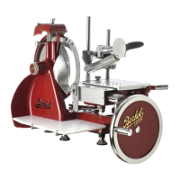
1. Remove clevis pin, then slide bar from clevis.
Fig. 62
2. Turn clevis in or out to adjust.
NOTE: On X13A units the slide bar activates a switch
on the slide bar guide when product table is installed.
Fig. 63
3. Check slicer for proper operation.
X13 SLICER - SERVICE PROCEDURES AND ADJUSTMENTS
F25332 Rev. A (0718) Page 24 of 36