3. Disconnect all lead wires to the board, noting
their color and location.
4. Remove control board.
5. Reverse procedure to install.
6. Check slicer for proper operation.
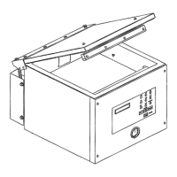
KICK STAND
Kick Stand Removal
Disconnect the electrical power to
the machine and follow lockout /
tagout procedures.
1. Place slicer on its side, so it is resting on motor
housing.
2. Remove spring and bolt securing kick stand to
slicer.
Fig. 48
3. Remove kick stand.
4. Reverse procedure to install.
5. Check slicer for proper operation.
GAUGE PLATE ASSEMBLY
Gauge Plate Assembly Removal
Disconnect the electrical power to
the machine and follow lockout /
tagout procedures.
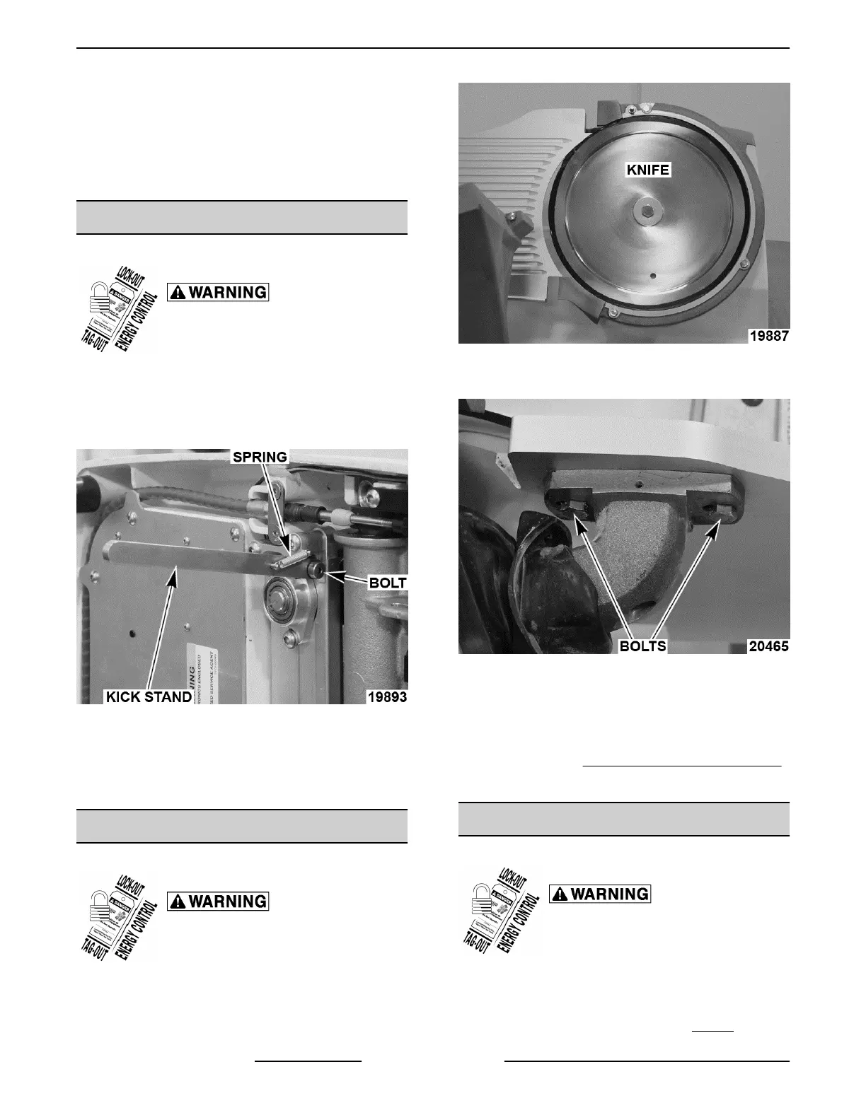
1. Open gauge plate and tape knife.
Fig. 49
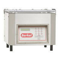
2. Remove gauge plate bolts.
Fig. 50
3. Remove gauge plate.
4. Reverse procedure to install.
5. Check that gauge plate is in adjustment as
outlined under GAUGE PLATE ADJUSTMENT .
6. Check slicer for proper operation.
INDEX MECHANISM
Index Mechanism Removal
Disconnect the electrical power to
the machine and follow lockout /
tagout procedures.
NOTE: Index mechanism can be ordered and
replaced as a whole assembly.
1. Remove knife as outlined under KNIFE.
X13 SLICER - REMOVAL AND REPLACEMENT OF PARTS
F25332 Rev. A (0718) Page 20 of 36