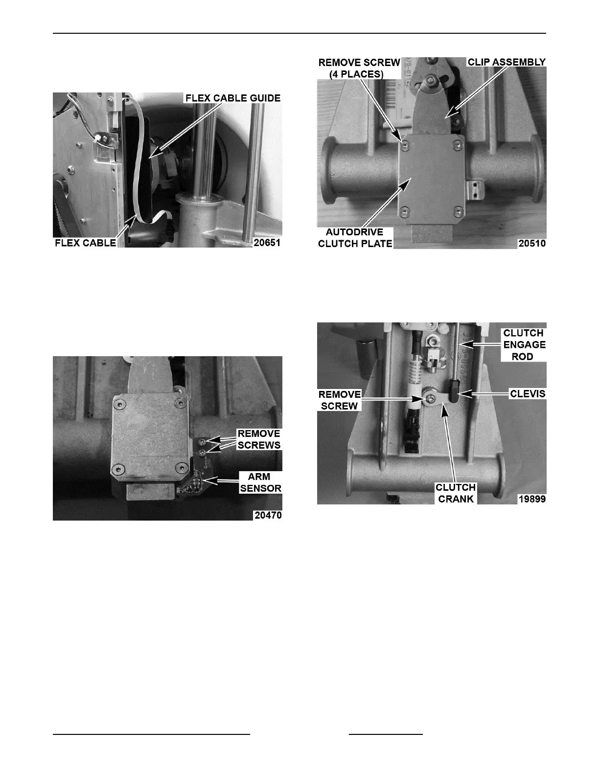
B. Reconnect flex cable last, and make sure
cable is in front of guide assembly. (X13A,
X13AE)
Fig. 14
13. Check slicer for proper operation.
Arm Disassembly
NOTE: Remove only those parts required to access
part(s) being replaced.
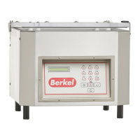
1. Remove screws and arm sensor.
Fig. 15
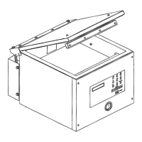
2. Remove autodrive clutch plate screws.
Fig. 16
3. Remove autodrive clutch plate and clip
assembly.
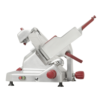
4. Remove screw, autodrive clutch crank, and
clutch engage rod.
Fig. 17
5. Remove autodrive clutch cam, clutch pivot shaft,
and spring disc.
X13 SLICER - REMOVAL AND REPLACEMENT OF PARTS
Page 11 of 36 F25332 Rev. A (0718)