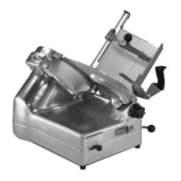
CARRIAGE SENSOR TEST (X13,
X13A)
Certain procedures in this section require
electrical test or measurements while power is
applied to the machine. Exercise extreme caution
at all times. If test points are not easily accessible,
disconnect power and follow lockout / tagout
procedures, attach test equipment and reapply
power to the test.
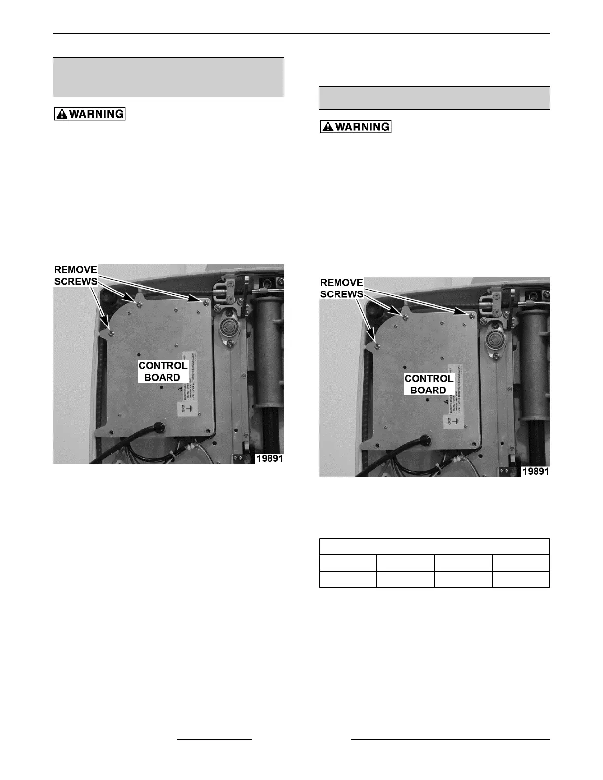
1. Place slicer on its side, so it is resting on motor
housing.
2. Remove screws to access control board.
Fig. 82
3. Plug slicer in.
4. Verify 5VDC supply voltage between J4-1 and
J4-5.
A. If voltage is not present, check all
connections.
B. If connections are good, replace control
board.
5. Verify 0VDC between J4-2 and J4-5 in manual
mode (clutch engage rod in).
6. Verify 5VDC between J4-2 and J4-5 in auto mode
(clutch engage rod out).
7. Verify 5VDC between J4-3 and J4-5 when arm
assembly is in home position.
A. 0VDC should be present anytime arm
assembly is away from home position.
8. If voltages are not all present, replace carriage
sensor.
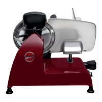
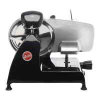
KNIFE MOTOR OHM TEST
Certain procedures in this section require
electrical test or measurements while power is
applied to the machine. Exercise extreme caution
at all times. If test points are not easily accessible,
disconnect power and follow lockout / tagout
procedures, attach test equipment and reapply
power to the test.
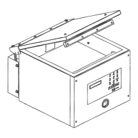
1. Place slicer on its side, so it is resting on motor
housing.
2. Remove screws to access control board.
Fig. 83
3. Connect a volt/ohm meter to both disconnected
motor lead wires (P1 and P2) and verify ohm
readings per chart.
MOTOR RESISTANCE
Volts Hertz Min. Max.
115 60 1.21 1.33
4. If ohm readings are out of spec, replace motor.
X13 SLICER - SERVICE PROCEDURES AND ADJUSTMENTS
F25332 Rev. A (0718) Page 30 of 36