1. Install knife motor as outlined under KNIFE
MOTOR AND MOUNT ASSEMBLY .
2. Pull belt tight and walk onto knife hub.
NOTE: Make sure belt is seated properly on motor
shaft grooves and knife hub. Knife belt should be
centered on knife hub and completely on motor shaft.
3. Check slicer for proper operation.
KNIFE HUB ASSEMBLY
Knife Hub Assembly Removal
Disconnect the electrical power to
the machine and follow lockout /
tagout procedures.
NOTE: Some knife hub assemblies are secured with
an e-clip instead of a nut.
1. Remove knife as outlined under KNIFE.
2. Remove autodrive assembly as outlined under
AUTODRIVE MECHANISM (X13A, X13AE).
3. Remove knife motor as outlined under KNIFE
MOTOR AND MOUNT ASSEMBLY.
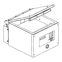
4. Remove screws securing knife hub assembly to
slicer wall.
Fig. 45
5. Supporting hub, tap knife end of assembly with a
rubber mallet.
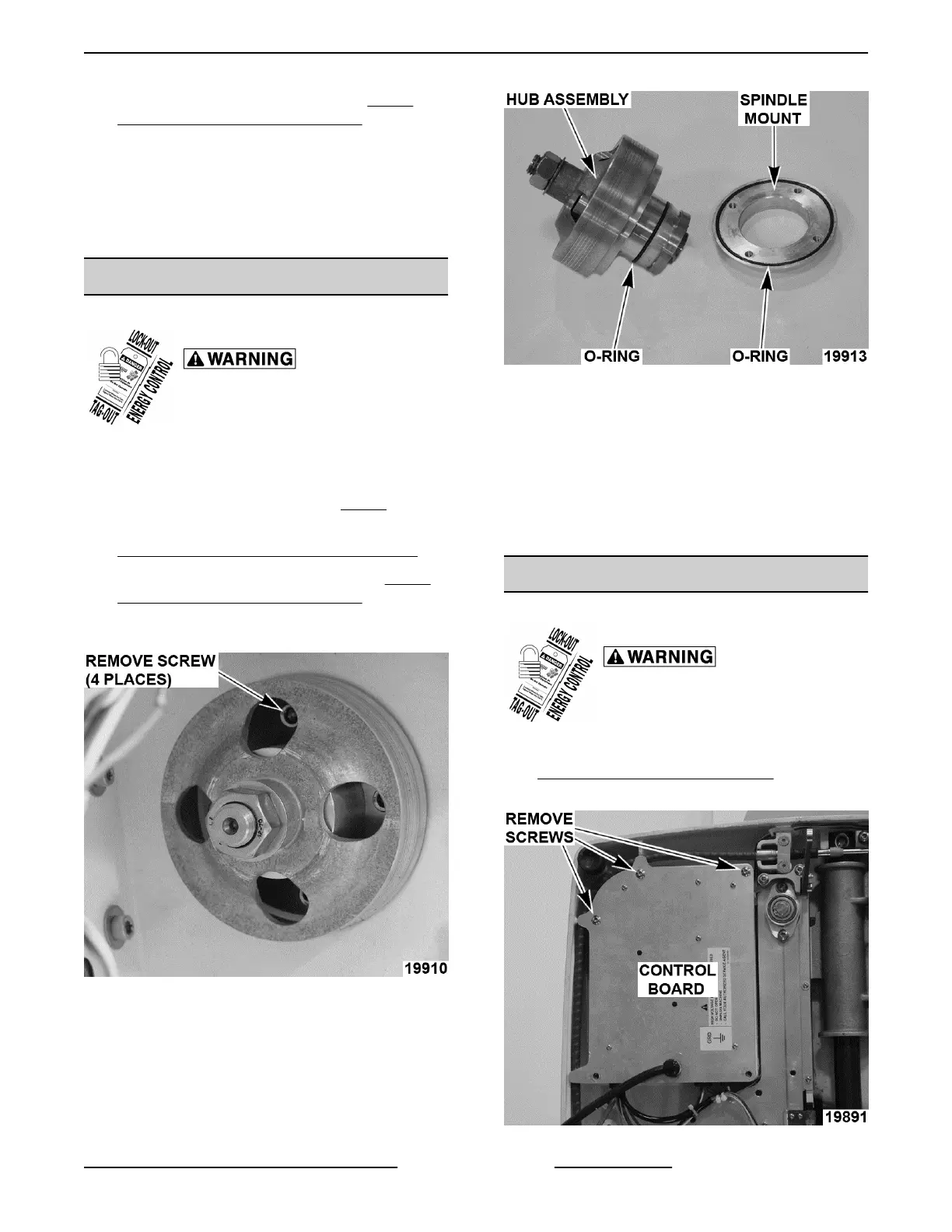
A. Remove hub assembly and spindle mount.
Fig. 46
6. Reverse procedure to install.
A. Lightly coat o-rings with Berkel.
NOTE: Line up screw holes when pressing spindle
mount onto hub assembly.
B. Torque bolts 50 in.-lbs.
7. Check slicer for proper operation.
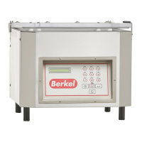
CONTROL BOARD
Control Board Removal
Disconnect the electrical power to
the machine and follow lockout /
tagout procedures.
1. Remove bottom cover as outlined under
BOTTOM COVER (X13A, X13AE).
2. Remove screws.
Fig. 47
X13 SLICER - REMOVAL AND REPLACEMENT OF PARTS
Page 19 of 36 F25332 Rev. A (0718)