bottom of gauge plate will increase. Maintain 1/8" gap
at center and an even gap top to bottom.
Fig. 67
C. Tighten bolts.
D. Place boot back into place and seal with
RTV.
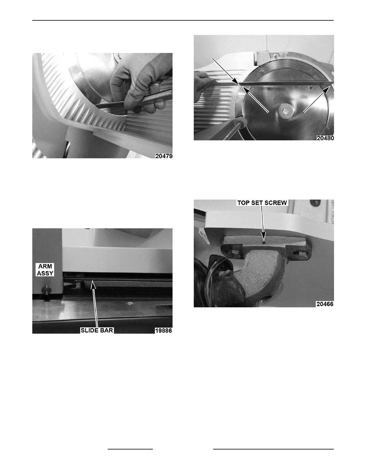
2. Gauge plate to knife angle.
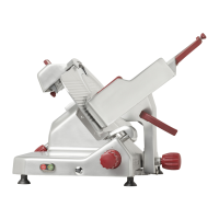
A. Remove center plate and pull slide bar
towards arm assembly to unlock index knob.
Fig. 68
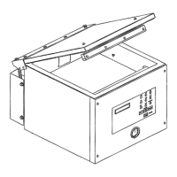
B. Turn index knob until 3 contact points are
met at top of gauge plate.
Fig. 69
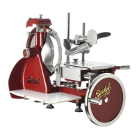
C. Pull rubber boot away from adjustment
block.
D. Loosen top and bottom set screws.
NOTE: Bottom set screw is underneath adjustment
block. (opposite top set screw)
Fig. 70
E. Loosen center bolt and adjust gauge plate
so that bottom is 0.015" above top of gauge
plate.
F. Tighten bolt and set screws.
G. Recheck that gauge plate is still in proper
adjustment.
H. Place boot back into place and seal with
RTV.
3. Gauge plate to knife height.
NOTE: Top of gauge plate should be 0.030" above
knife when fully closed.
X13 SLICER - SERVICE PROCEDURES AND ADJUSTMENTS
F25332 Rev. A (0718) Page 26 of 36