EasyManua.ls Logo

BestCode NExT 82 - Page 140

Default Icon
305 pages
Print Icon
To Next Page IconTo Next Page
To Previous Page IconTo Previous Page
Loading...
BestCode Next Series 8 Technical Manual October 2022 Page 126 of 290
Parallel
Wiring the Parallel Kit
Pin Position
Function
Pin Position
Function
Pin Position
Function
1
24V
7
RELAY NC
13
MESSAGE SELECT 6
2
MESSAGE SELECT 1
8
24V
14
GROUND
3
MESSAGE SELECT 3
9
PHOTOEYE PNP
15
RELAY COMMON
4
MESSAGE SELECT 5
10
MESSAGE SELECT 0
16
GROUND
5
MESSAGE SELECT 7
11
MESSAGE SELECT 2
17
PHOTOEYE NPN
6
RELAY NO
12
MESSAGE SELECT 4
18
GROUND
Instructions:
1) From back of bulkhead fitting, strip and solder 18 wires (22awg) of 300mm length (12”) into the fitting.
a. Individually sleeve each solder joint for maximum protection
2) Strip and apply crimp to end of each wire.
3) Install crimps into the Molex Housing.
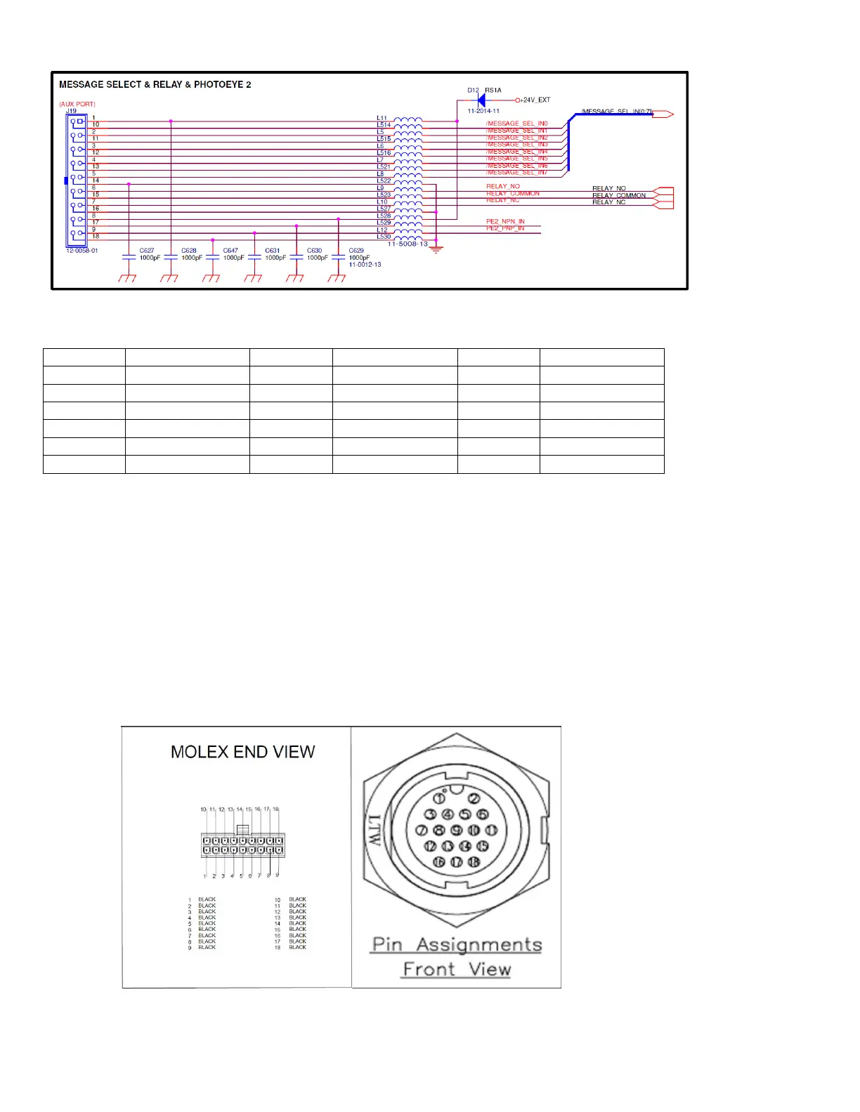
a. Mate crimps 1-1 from Bulkhead fitting to the Molex Housing.
4) Install the Cable assembly into the Series 8 System using the “Parallel” bulkhead knockout on the side of the
machine.
5) Repeat the process for the device side, matching device features to the corresponding pins.
a. Use the provided seal and grommet to ensure cable maintains IP 67 Rating.

Table of Contents

Related product manuals