12’–24’ BASIC6
™
WWW.BIGASSFANS.COM ©2012 DELTA T CORP. DBA BIG ASS FAN ALL RIGHTS RESERVED
6
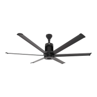
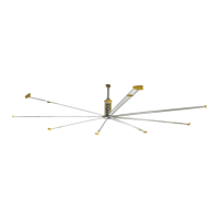
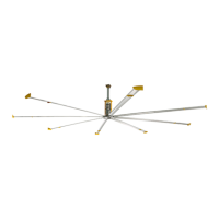
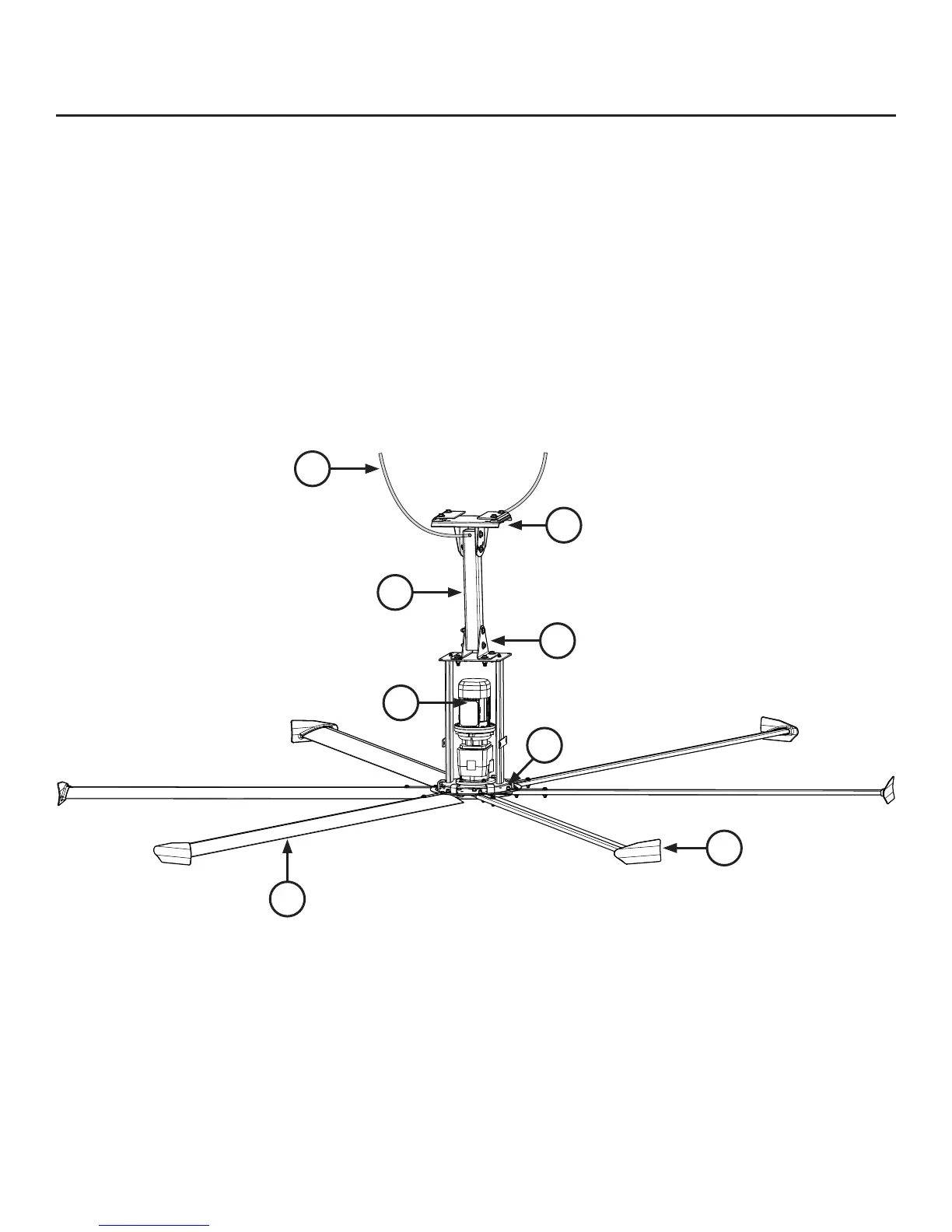
Fan diagram
A. Safety Cable. A redundant safety feature that secures the fan to the mounting structure.
B. Upper Yoke. Secures the fan to the mounting structure and allows the fan to adjust its center of gravity. Note: The upper yoke may
differ from the illustration below.
C. Extension Tube. Extends the fan from the ceiling.
D. Lower Yoke. Connects main fan unit to the extension tube.
E. Motor. 6HHSDJHIRUWHFKQLFDOVSHFL¿FDWLRQV
F. Hub. Secures the airfoils to the gearbox.
G. Airfoil. 3URYLGHVDLUPRYHPHQW7KHXQLTXHSDWHQWHGGHVLJQSURYLGHVHI¿FLHQF\DQGHIIHFWLYHDLUPRYHPHQW
H. Winglet. ,PSURYHVWKHHI¿FLHQF\RIWKHIDQ
Pre-Installation (cont.)
F
H
E
C
D
B
A
G