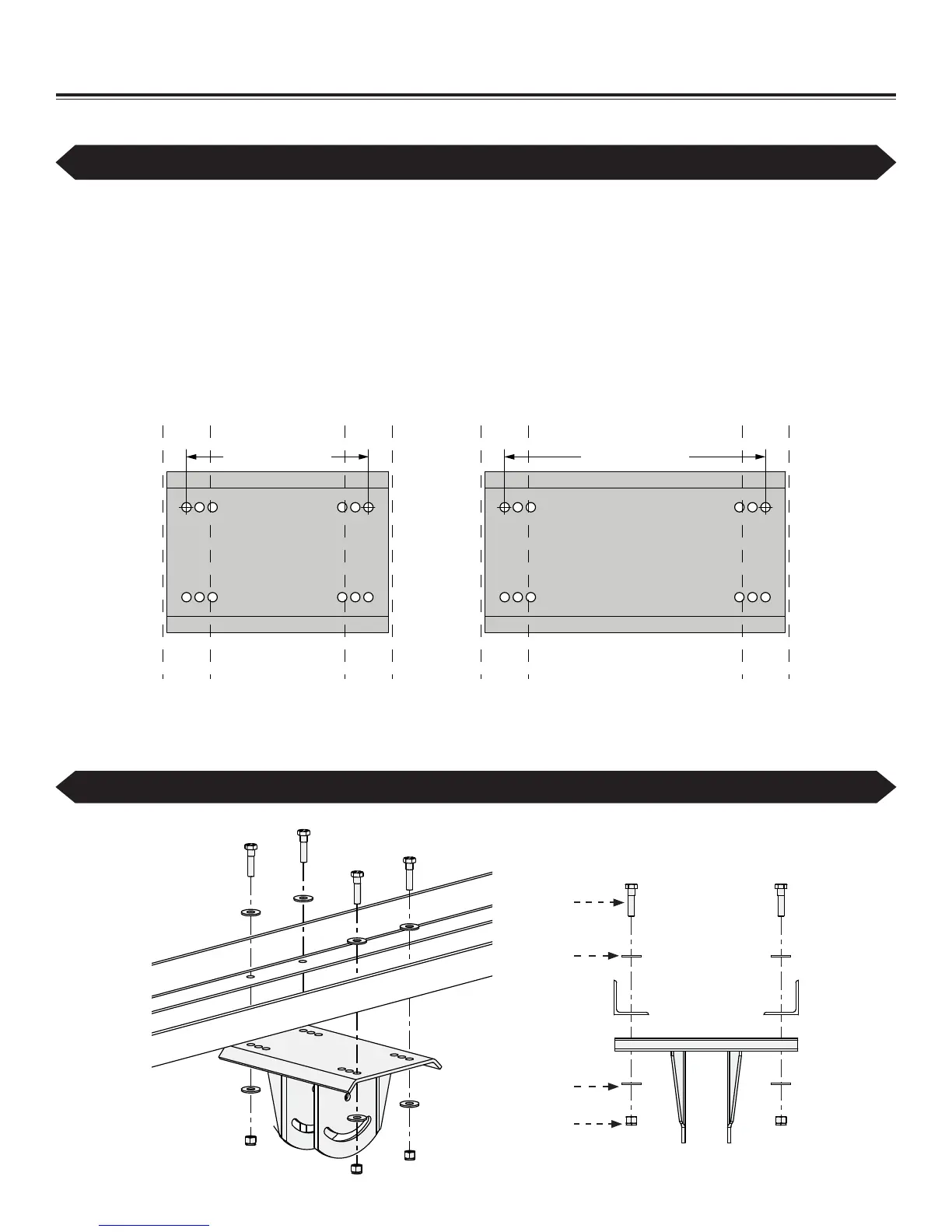
Small Upper Yoke
13 1/4’’ (33.7cm) x
9 5/8” (24.4cm)
Large Upper Yoke
18’’(45.7cm) x
9 5/8”(24.4cm)
10-7/8" (27.6cm) 15-5/8" (39.7cm)
17
WWW.BIGASSFANS.COM ©2012 DELTA T CORP. DBA BIG ASS FAN ALL RIGHTS RESERVED
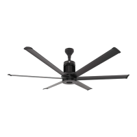
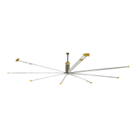
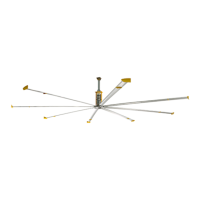
12’–24’ BASIC6
™
5a. Attach upper yoke (to angle irons)
Secure the upper yoke directly to the angle irons with the Upper Yoke Hardware as shown. The angle irons should be aligned with the
outermost holes of the upper yoke. Consult the diagrams below for distances between the angle irons.
Tighten the bolts to 40 ft·lb (54.2 N·m) using a torque wrench and 3/4” socket. After attaching the upper yoke to the angle irons, tighten
all the bolts securing the angle irons to the roof structure to 40 ft·lb (54.2 N·m).
3URFHHGWR³+DQJLQJWKH)DQ´S
Upper Yoke Hardware (BAF-Supplied):
a. (4) 1/2”-13 x 2” GR 8 Bolt
b. (8) 1/2’’ Flat Washer
c. (4) 1/2-13 Nylock Nut
Mounting Structure: Bar Joists (cont.)
If the fan will be directly mounted to the angle irons, skip this step and proceed to step 5b.
The angle irons should be aligned with the outermost holes on the upper yoke. Do not use beam clips on angle irons!
Note: Dashed lines represent angle irons.
Side View
a
b
c
b