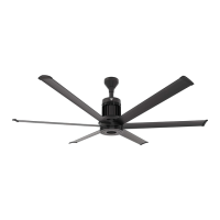
12’–24’ BASIC6
™
WWW.BIGASSFANS.COM ©2012 DELTA T CORP. DBA BIG ASS FAN ALL RIGHTS RESERVED
30
Wiring: ESFR (Early Suppression Fast Response)
WARNING: Wait three minutes after disconnecting before servicing!
:$51,1*,PSURSHULQVWDOODWLRQFDQFDXVHHOHFWULFVKRFNRUGDPDJHWRWKHPRWRUDQGFRQWUROOHU$TXDOL¿HGHOHFWULFLDQ
should perform the installation.
AVERTISSEMENT : Attendez trois minutes après avoir débranché avant d’utiliser le regulateur !
AVERTISSEMENT : Une installation incorrecte peut provoquer un choc électrique ou endommager le moteur et le
UpJXODWHXU8QpOHFWULFLHQTXDOL¿pGRLWHIIHFWXHUO¶LQVWDOODWLRQ
ATTENTION: If installing the fan in the United States, the fan must be installed per the following National Fire Protection
Association (NFPA) guidelines:
The fan must be centered approximately between four adjacent sprinklers.
7KHYHUWLFDOGLVWDQFHIURPWKHIDQWRWKHVSULQNOHUGHÀHFWRUPXVWEHDWOHDVWIWFP
7KHIDQPXVWEHLQWHUORFNHGWRVKXWGRZQLPPHGLDWHO\XSRQUHFHLYLQJDZDWHUÀRZVLJQDOIURPWKHDODUPV\VWHP
7KH¿UHUHOD\LQFOXGHGZLWKWKHIDQLVQHHGHGRQO\LIWKHIDQZLOOEHLQVWDOOHGLQDEXLOGLQJWKDWKDVD¿UHVSULQNOHUV\VWHP7KH¿UHUHOD\
integrates the fan with the sprinkler system and shuts down the fan upon receiving an alarm signal from the system. If the building in
which the fan will be installed has a sprinkler system, you must install the relay according to the instructions below.
A contact closure across the digital input terminals 4 and 13A will result in fan shutdown. The included relay uses a Normally Open
12FRQWDFWDVVKRZQEHORZ7KHUHOD\FRLOPXVWEHHQHUJL]HGE\WKH)$&3IRUIDQVKXWGRZQ2SWLRQDOO\WKHQRUPDOO\FORVHG1&
UHOD\FRQWDFWFDQEHXVHG7KHUHOD\FRLOPXVWUHPDLQHQHUJL]HGE\WKH)$&3IRUIDQRSHUDWLRQ7KLVZRXOGEHFRQVLGHUHGDIDLOVDIHRU
fail open wiring arrangement. Two additional relay coil leads are provided to facilitate supervision pass-through where required.
Electrical Installation (cont.)
U/T1 V/T2 W/T3
PE
L1 L2 L3
1 2 5 6 13A 13B 13C 1 4 3 0 1 6 1725 4 11
1 2 5 6 13A 13B 13C 1 4 3 0 1 6 1 725 4 11
L1
L2
L3
PAM-SD
(-)
(+)
C
NC
NO
From Main FACP or
NAC Box if Applicable.
M
RF
RUN
STOP
AUTO FWD
REV
Relay Coil/Contact Details
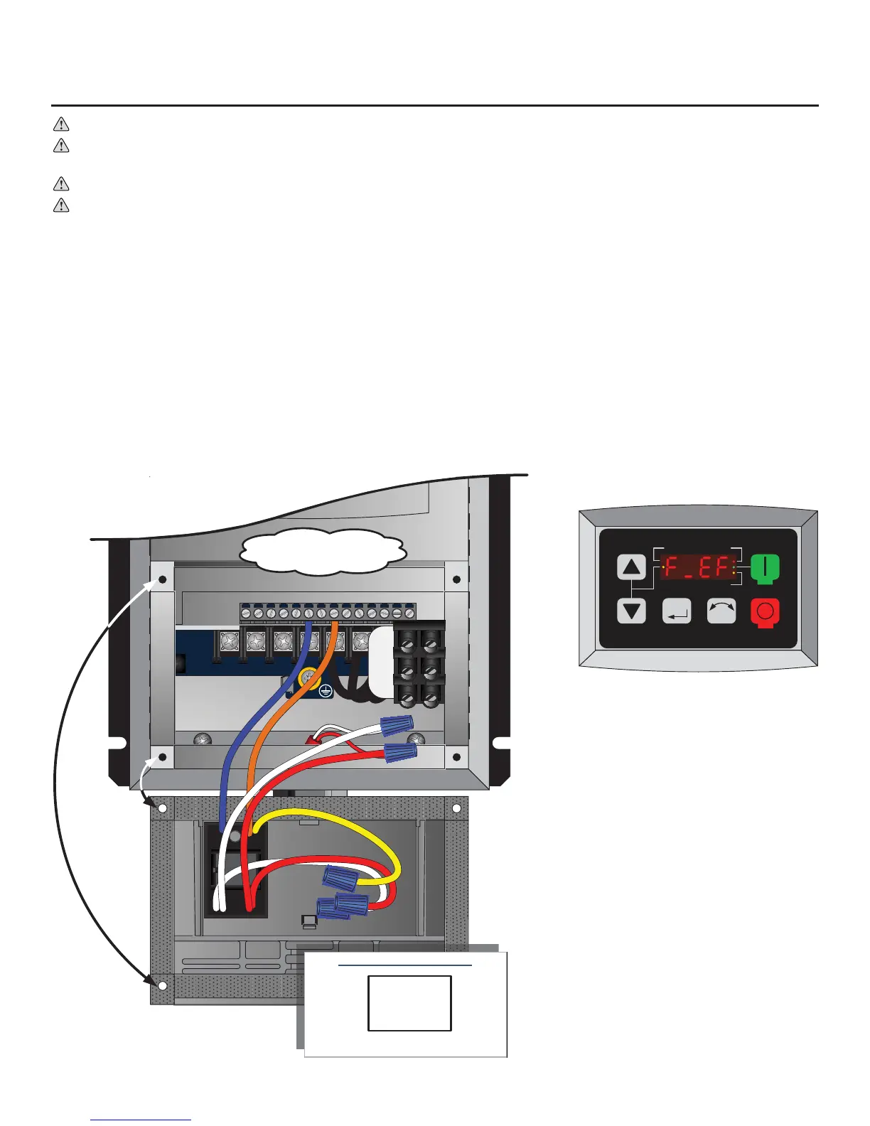
White (X2)
Red (X2)
Orange
Yellow
Blue
Coil: 20-32VDC @ 20mA
Terminals 4 & 13A
for ESFR Relay
Relay is mounted to the
backside of the access cover.
An alarm condition will stop the fan and
issue an “F_EF” external fault on the fan
controller’s display.