25
WWW.BIGASSFANS.COM ©2012 DELTA T CORP. DBA BIG ASS FAN ALL RIGHTS RESERVED
12’–24’ BASIC6
™
Electrical Installation (cont.)
Electrical installation overview
The electrical installation section is intended for a professional electrician. If you are unfamiliar or uncomfortable with installing electrical
components, do not attempt to install the fan without an electrician. Serious personal injury or damage to the fan and other equipment
could result. This guide is merely a recommendation of proper installation. Adhering to national and local electric codes is your
UHVSRQVLELOLW\,WLVWKHVROHUHVSRQVLELOLW\RIWKHLQVWDOOHUWRYHULI\WKHRSHUDWLQJYROWDJHRIWKHIDQV\VWHPSULRUWRLQVWDOODWLRQ,WLVDOVR
mandatory that the installer verify that airfoils, motor assemblies, and fan controllers are matched properly at the time of installation,
especially if multiple fan systems will be installed.
The following sections outline how to prepare for the electrical installation, and include the required cables and how to properly route
the cabling through conduit, how to properly ground the fan system, how to properly wire the fan controller, how to properly wire the fan
motor, and proper startup procedures.
Controller storage
Store the controller within an ambient temperature range of -40°F to 185°F (-40°C to 85°C) and a relative humidity range of 0 to 95%,
non-condensing. Do not expose the controller to a corrosive atmosphere. If the controller has been in storage or disconnected from
power for more than one year, apply AC supply power to the controller for a period of two hours prior to operation in order to recondition
the internal DC bus capacitors.
Power requirements for fan controllers
The power requirements for fan controllers are listed in the table on p. 2. If multiple controls are connected to one feeder circuit, the
circuit required is the sum of the feeder circuit requirements listed on the chart. This type of installation will also require that each fan
control be installed downstream from a dedicated over-current protection device.
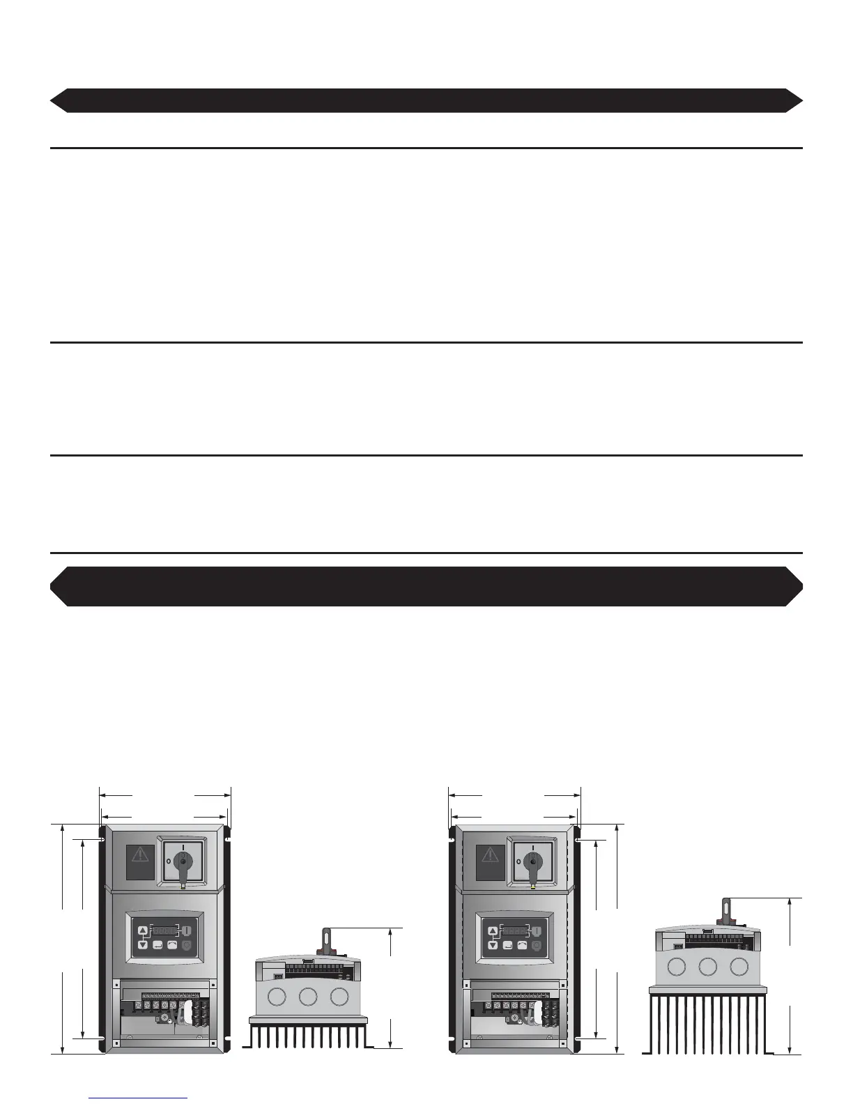
Mounting the wall controller
Mount the controller to a wall using a #8–#10 screw. Adhere to the following guidelines when selecting the controller location:
,QVWDOOWKHFRQWUROOHURQDÀDWVXUIDFHWKDWLVUHDGLO\DFFHVVLEOHIUHHIURPYLEUDWLRQDQGZKHUHWKHUHLVDGHTXDWHGLVWDQFHIURPIRUHLJQ
objects or moving equipment.
Do not mount any controller adjacent to or above a heat source or heat-producing equipment.
The ambient temperature must be between 14º F (-10º C) and 122º F (50º C).
Do not expose the controller to a corrosive atmosphere, moisture, or direct sunlight.
When mounting the controller, keep in mind that the fan should be visible from the controller.
A minimum distance of 6” (15.2 cm) should be maintained between fan controllers.
2 HP Controller1 HP Controller
U/T1 V/T2 W/T3
PE
L1 L2 L3
L1
L2
L3
1256 13A13B13C1430161725 4 11
1 2 5 6 13A13B 13C 1 4 30 1 6 1 725 4 11
SC A M E
SC A M E
M
RF
RUN
STOP
AUTO FWD
REV
U/T1 V/T2 W/T3
PE
L1 L2 L3
L1
L2
L3
1 2 5 6 13A13B13 C 14 30 16 1725 4 11
1 2 5 6 13A13B 13C 1 4 3 0 1 6 1 725 4 11
SC A M E
SC A M E
M
RF
RUN
STOP
AUTO FWD
REV
WARNING
DO NOT USE THIS
DISCONNECT TO
START AND STOP THE
FAN. PERMANENT
DAMAGE WILL
RESULT!
WARNING
DO NOT USE THIS
DISCONNECT TO
START AND STOP THE
FAN. PERMANENT
DAMAGE WILL
RESULT!
9.5” (241 mm)
10.9” (277 mm)
5.51” (140 mm)
9.5” (241 mm)
10.9” (277 mm)
5.95” (151 mm)
7.3” (185 mm)
6.25” (159 mm)
5.95” (151 mm)
6.25” (159 mm)
If you are mounting the controller to the fan motor frame instead of the wall (onboard VFD option), skip this section and
refer to the mounting instructions that came with the wall controller and hardware for the onboard VFD.
If you are installing an onboard variable frequency drive (VFD), ensure you route the power wiring to the fan location.