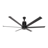
12’–24’ BASIC6
™
WWW.BIGASSFANS.COM ©2012 DELTA T CORP. DBA BIG ASS FAN ALL RIGHTS RESERVED
34
Daisy chaining
WARNING: Wait three minutes after disconnecting before servicing!
AVERTISSEMENT : Attendez trois minutes après avoir débranché avant d’utiliser le regulateur !
The following illustrations and parameter changes enable daisy chaining of the Basic6
™
IDQVSHHGFRQWUROOHU7KH¿UVWIDQSURYLGHVD
VWDUWVWRSFRQWDFWDQG±9'&DQDORJVSHHGUHIHUHQFHIRUWKHGRZQVWUHDPIDQFRQWUROOHU7KHGRZQVWUHDPIDQFRQWUROOHUSURYLGHV
DQHZVWDUWVWRSFRQWDFWDQG±9'&DQDORJVSHHGUHIHUHQFHIRUWKHIROORZLQJGRZQVWUHDPIDQFRQWUROOHU7KLVSUHIHUUHGPHWKRGRI
linking the fan controllers together ensures minimal signal loss of command signals in larger multi-fan systems.
Assertion Level Switch (ALSW)
7KHIDQFRQWUROOHUVKLSVZLWKWKHRQERDUGGLJLWDO,2FRQ¿JXUHGIRU6RXUFLQJ313RSHUDWLRQ7HUPLQDOSURYLGHV9'&WREH
used as a supply voltage for user-supplied switches and accessories. For this 3-wire daisy chaining application, the downstream fan
controllers must be switched to Sinking (NPN) operation. Terminal 4 will then provide a DC common connection and allow the analog
signal and start stop signal to share that common. The Assertion Level Switch above terminal 4 must be switched from (+) to ( - )
on all downstream fan controllers for proper daisy chaining operation prior to powerup, parameter changes and operation.
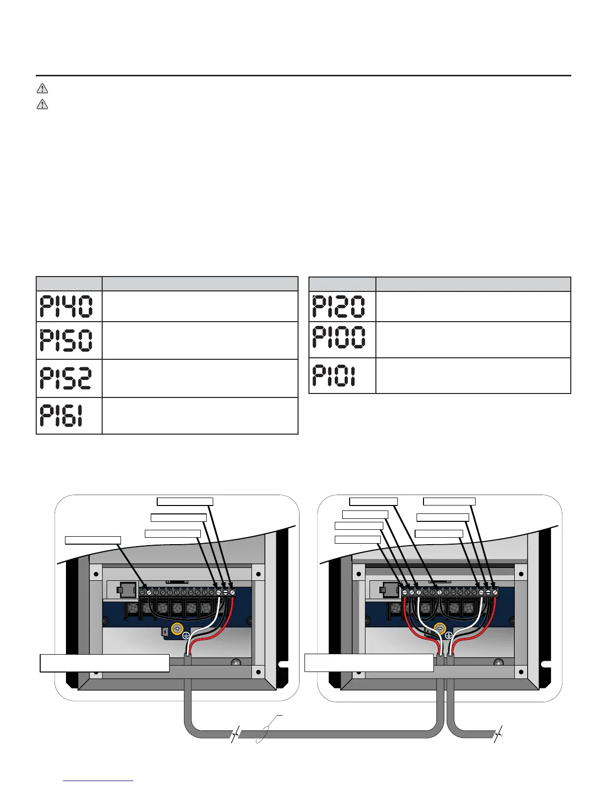
3DUDPHWHUFKDQJHVIRU¿UVWFRQWUROOHU
Parameter Description
Relay Output Function
Change from “0” for None to “1” for Run.
TB-30 Output
&KDQJHIURP³´IRU1RQHWR³´IRU±9'&
output (scaled to drive output frequency).
TB-30 Scaling Frequency
Change to equal the frequency setting of P103
Maximum Frequency.
Speed at Max Signal
Change to equal the frequency setting of P103
Maximum Frequency.
1RWH'HSHQGLQJRQWKH$:*DQGGLVWDQFHRIWKHORZYROWDJHZLULQJWKHGRZQVWUHDPIDQVPD\UXQVOLJKWO\VORZHUWKDQWKHOHDGLQJIDQ
,IWKLVRFFXUV36SHHGDW0D[6LJQDOFDQEHXVHGWRLQWURGXFHDPLQRUFRPPDQGUHIHUHQFHRYHUVKRRWWRFRPSHQVDWHIRUWKHDQDORJ
YROWDJHGURS$WHDFKGRZQVWUHDPIDQEHJLQQLQJZLWKWKH¿UVWGRZQVWUHDPIDQDGMXVWWKHYDOXHRI3XSWR+]LQFUHPHQWV
until the fan’s output frequency matches that of the lead fan.
Electrical Installation (cont.)
3 conductor shielded cable minimum 20AWG Stranded
(provided by installer) Recommended Maximum distanceсϮϬϬŌ
U/T1 V/T2 W/T3
PE
L1 L2 L3
1 2 5 6 13A 13B 13C 14 30 16 1725 4 11
1 2 56 13A13B13C1430 16 1725 4 11
U/T1 V/T2 W/T3
PE
L1 L2 L3
1256 13A13B13C1430 16 1725 4 11
1256 13A 13B 13C 14 30 16 1725 4 11
0–10VDC and Start/Stop
out to next downstream
controller
#30 = 0–10VDC Output
#16 = N.O. Relay Output
#17 = N.O. Relay Output
#2 = Analog Common
#30 = 0–10VDC Output
#16 = N.O. Relay Output
#17 = N.O. Relay Output
#5 = 0–10VDC Input
#4 = Digital Common*
#1 = Run/Stop Input
#2 = Analog Common
Terminals 2, 4 and 16 shall all be tied
together on all downstream fan controllers.
Terminals 2 and 16 shall all be tied together
on the first fan controller.
Parameter changes (for downstream controllers)
Parameter Description
Assertion Level
Change from “2” for High to “1” for Low.
Start Control Source
Change from “0” for keypad operation to “1” for
Terminal Strip.
Standard Reference Source
Change from “0” for keypad operation to “1” for
±9'&DQDORJLQSXWRSHUDWLRQ