35
WWW.BIGASSFANS.COM ©2012 DELTA T CORP. DBA BIG ASS FAN ALL RIGHTS RESERVED
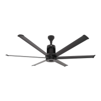
12’–24’ BASIC6
™
Electrical Installation (cont.)
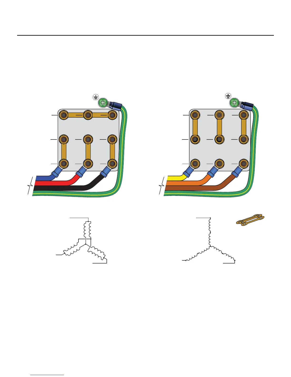
:LULQJWKHPRWRUOHDGGXDOYROWDJHZ\HPRWRUFRQ¿JXUDWLRQV
7KHPRWRUZLULQJFRQ¿JXUDWLRQVVKRZQEHORZDUHDSSOLFDEOHWROHDGGXDOYROWDJHZ\HZRXQGPRWRUVUDWHGIRU9$&DQG
9$&&RQVXOWWKHPRWRUQDPHSODWHDQGRUZLULQJSODFDUGIRUYHUL¿FDWLRQRIUHTXLUHGZLULQJFRQQHFWLRQV0RWRUVZLWKWHUPLQDO
blocks require ring terminals and a 7 mm nut driver for termination. The diagrams below include L2 and L3 swap to yield proper motor
rotation. Note: Swapping leads to reverse rotation is done only on the output side of the drive.
U1
T1
V1
T2
W1
T3
U5
T7
V5
T8
W5
T9
U2
T4
V2
T5
W2
T6
VAC from VFD
Low V oltage
High Voltage
U1
T1
V1
T2
W1
T3
U5
T7
V5
T8
W5
T9
U2
T4
V2
T5
W2
T6
VAC from VFD
BLUE
RED
BLACK
GREEN W/ YELLOW TRACER
YEL
ORANGE
BROWN
GREEN W/ YELLOW TRACER
Low Voltage
±9$&±+]
±9$&±+]
High Voltage
±9$&±+]
±9$&±+]
Jumper bars are
provided with the
motor