CB-S / CB-S-UL (E7) 06/2020 page 104/119
26. Technical description
26.1 Factory calibration and adjustment
This chamber was calibrated and adjusted in the factory. Calibration and adjustment were performed
using standardized test instructions, according to the QM DIN EN ISO 9001 system applied by BINDER
(certified since December 1996 by TÜV CERT). All test equipment used is subject to the administration of
measurement and test equipment that is also a constituent part of the BINDER QM DIN EN ISO 9001
systems. They are controlled and calibrated to a DKD-Standard at regular intervals.
A record of this calibration and adjustment is part of the BINDER test certificate of the chamber.
Adjustment in factory:
• Temperature: 37 °C / 98.6 °F measured in the center of the usable volume
• CO
2
: 0 vol.-% CO
2
(100 vol.-% N
2
) and 5 vol.-% CO
2
(sensor head directly exposed to analyzed test
gas)
Repeated calibrations are recommended in periods of 12 months.
Suitable reference methods applicable for the user for comparison between reference measuring results
and the display readings of the controller(s) are explained in chap. 19.
During factory calibration and adjustment, an electronic temperature measuring and display device is
used, which is traceable to an acknowledged standards/calibration institution (DKD or PTB for Germany),
bearing a valid calibration certificate.
During factory calibration and adjustment, test gases with an analyzed concentration and with adapted
flow quantity serve to calibrate the sensor system for CO
2
. The sensor head is exposed directly to the test
gas.
26.2 Over current protection
A miniature fuse accessible from the outside protects the device against over current. The miniature fuse
is located at the rear of the chamber below the strain relief of the power cord. The fuse holder is equipped
with a fuse clip 5mm x 20 mm. Replace the fuse only with a substitute of the same ratings. Refer to the
technical data of the respective device type. If the fuse is blown, please inform an electronic engineer or
BINDER service.
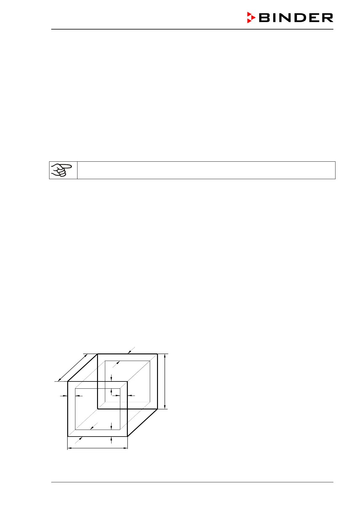
26.3 Definition of usable volume
The usable volume illustrated below is calculated as follows:
A, B, C = internal dimensions (W, H, D)
a, b, c = wall separation
a = 0.1*A
b = 0.1*B
c = 0.1*C
V
USE
= (A - 2 * a) * (B - 2 * b) * (C - 2 * c)
Figure 22: Determination of the useable volume
 Loading...