Issue 06/2020 Art. No. 7001-0402
Operating Manual
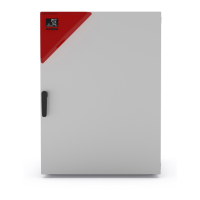
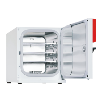
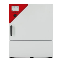
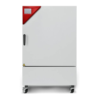
CB-S / CB-S-UL (E7)
CO
2
Incubator
with FPI-sensor system and RD4 controller
Model Model version Art. No.
CB-S 170 CBS170-230V 9040-0189, 9140-0189
CB-S 170-UL CBSUL170-120V 9040-0190, 9140-0190
CB-S 260 CBS260-230V 9040-0191, 9140-0191
CB-S 260-UL CBSUL260-120V 9040-0192, 9140-0192
BINDER GmbH
Address: Post office box 102, 78502 Tuttlingen, Germany Phone: +49 7462 2005 0
Fax: +49 7462 2005 100 Internet: http://www.binder-world.com
E-mail: info@binder-world.com Service Hotline: +49 7462 2005 555
Service Fax: +49 7462 2005 93 555 Service E-Mail: service@binder-world.com
Service Hotline USA: +1 866 885 9794 or +1 631 224 4340 x3
Service Hotline Asia Pacific: +852 390 705 04 or +852 390 705 03
Service Hotline Russia and CIS: +7 495 988 15 16