User’s Guide
Bus Expansion A robot can have legs, a head, and sometimes a tail. Thus sometimes there will be
a need for more 3 line bus connectors on the CM-5. In such cases a bus
expansion board can be used (connector expansion board is not included in the
beginner’s kit.)
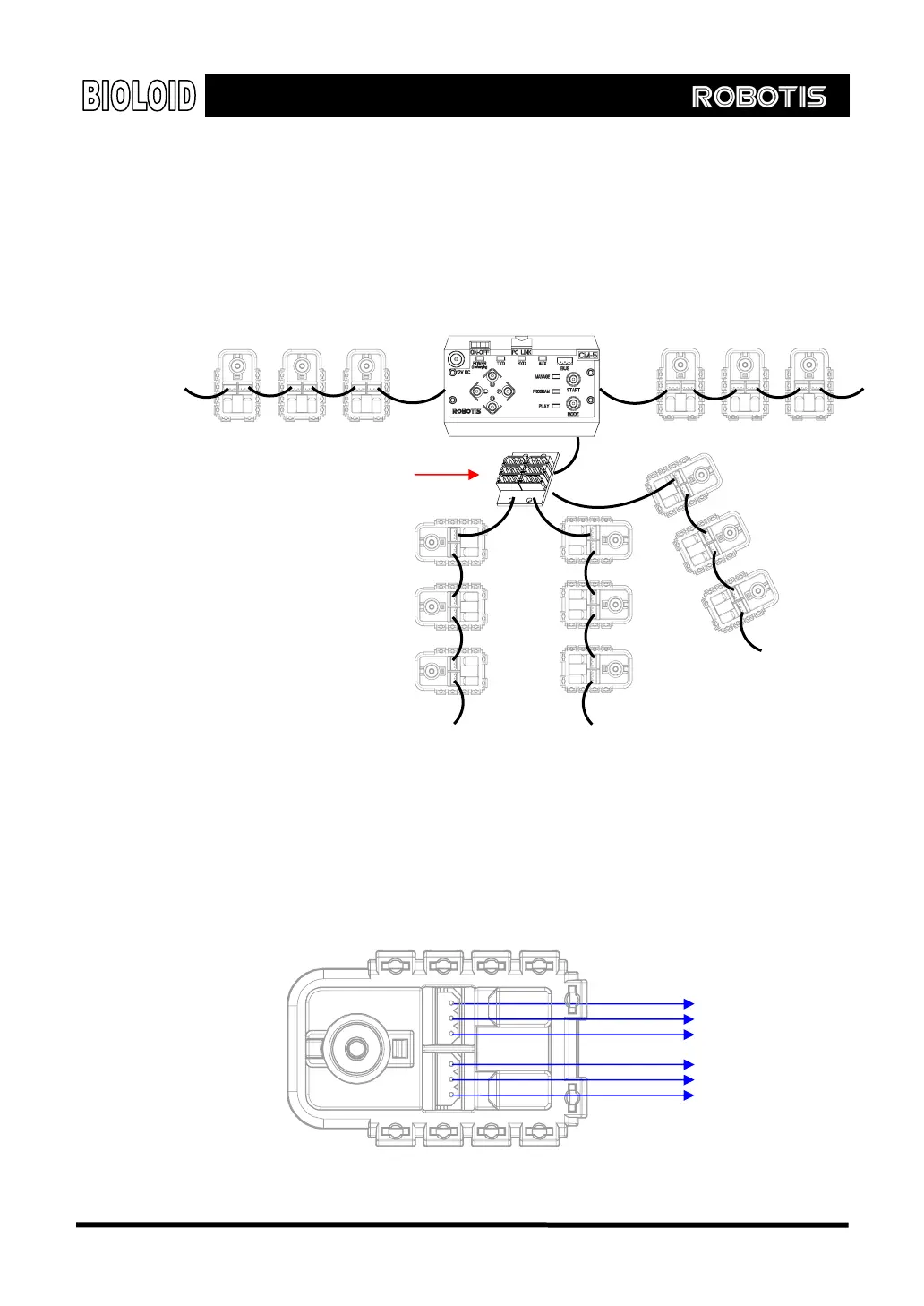
The figure below shows how the connector expansion board is used in wiring.
Connector expansion board
Arrangement of Pins
The figure below shows how the pins on a Dynamixel unit are arranged. Two of
the connectors inside the Dynamixel are connected pin to pin. This is how
connecting in a daisy chain configuration is possible. Pin1 and Pin 2 are where the
wires for the power source are connected. Make sure that the wires are
connected securely.
PIN2: VDD
PIN1: GND
PIN3: Data
PIN1: GND
PIN2: VDD
PIN3: Data
34