User’s Guide
values one by one, you can select “all Dynamixels” and assign values to all the
Dynamixels at once. In crossing gate, we use one Dynamixel. However for robots
that use many joints, you can take advantage of “all Dynamixel.” Refer to the
QuickStart for crossing gate example program.
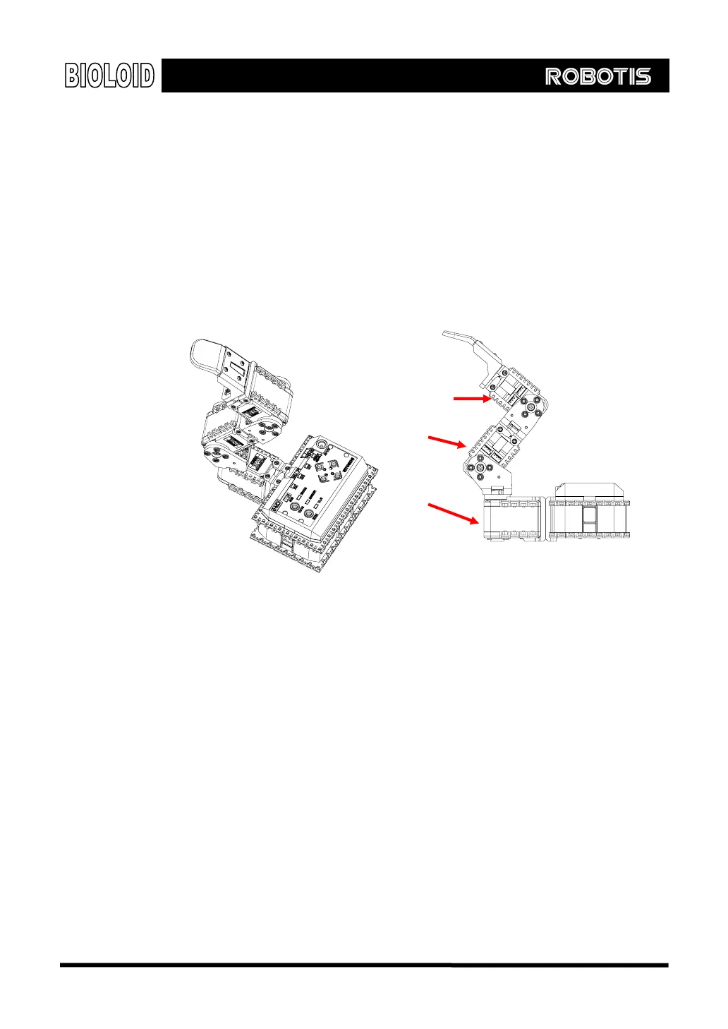
3-4. Assembling Robot Arm
Example Now that we have learned the basics of building, let’s go ahead and build a robot
arm. First, refer to the “2-2-8. Robot Arm” of QuickStart and build a robot arm.
ID=2
ID=3
ID=1
[Side view]
After you are finished building, make sure that the cables that come out from the
CM-5 bus and into the Dynamixels are all connected properly.
After you are finished building the arm, apply power to the CM-5 unit. Plug in the
power jack into the SMPS and turn the power switch on. The blinking of the
Dynamixel’s LED means that the power has been applied properly.
If the LED does not blink, then check the following.
Is the CM-5 unit in standby mode? (make sure the mode LED is blinking) If not, it
means that the power was not supplied properly.
Are the Dynamixels connected properly? Make sure the wiring on the AX-12 units
is done properly. The direction of the three line cables does not matter.
Charging Once the SMPS is connected the robot it can use the outside power source and
also recharge the internal batteries at the same time. Pressing the ○
U
button in
standby mode will start the recharging. Among the status LED’s of the CM-5 unit,
37