User’s Guide
2-4. Understanding ID, Address, and Data
So far we have learned how to create a simple behavior control program. Now
let’s systematically learn about the available input and output items.
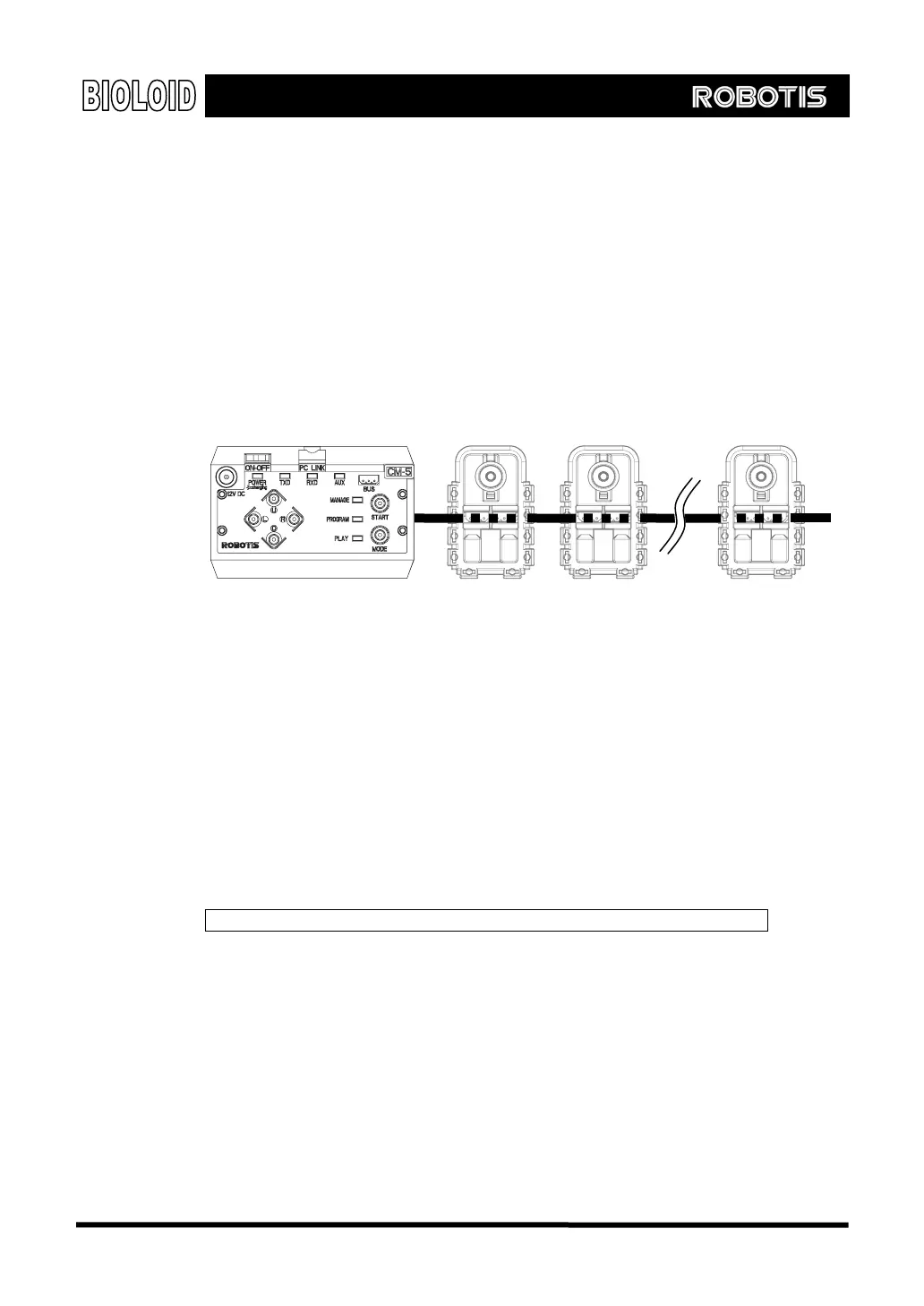
ID As mentioned previously, the Bioloid is made up of Dynamixel units and a CM-5
unit. The input and output items all exist inside these devices. All of these robot
modules are connected to one bus and each of them have their own unique ID.
CM-5
ID = 1
Address Each Dynamixel units has many input and output items. To access them, each item
is numbered in consecutive order. These numbers are called addresses.
Data Data is the value of each input and output item. If you look at the behavior control
program created previously (Button and LED). bpg, you can see that the LED is
located in the LED item (Address 24) of the CM-5 (unit with ID = 200). We have
made an “If” statement to see if the data it contains is 8 (the data value for
the ○
U
button). Let’s review the behavior control program again and look at the
“If” statement with this fact in mind.
Setting the input and output items means specifying the ID and address.
The Bioloid has three units: CM-5, AX-12, and AX-S1. Let take a look at the
available input and output items.
ID Assignment The following are the IDs that are assigned to each unit.
AX-12: ID = 1 ~ 19 (allowed range is 0~30)
AX-S1: ID = 100 (allowed range is 100~109)
CM-5: ID = 200
ID = 200 ID = 2 ID = N
27