BP-007 User’s Manual
- 34 -
Table A-1 Definition of the Cash drawer Connector Pins
Pin NO. Signal Name Electric Characteristic Signal Direction
1 Frame GND
2 Cash drawer drive signal DC24V/1A Output
3 Cash drawer Open/close signal TTL Input
4 24VDC Power
5 NC
6 Cash drawer Open/close signal GND
Drive current≤24V/1A
Note: Please use the proper cash drawer. Manufacturer will not honor warranty when using
improper cash drawer.
5.2.2 Parallel Interface
(1) Technology specifications
a) Select pulse: Pulse is supplied from exterior/STROBE.
b) Signal exchange: /ACK (answer) and BUSY (busy).
c) Logic electric level: All the input data and interface control signal are compatible with TTL electric
level.
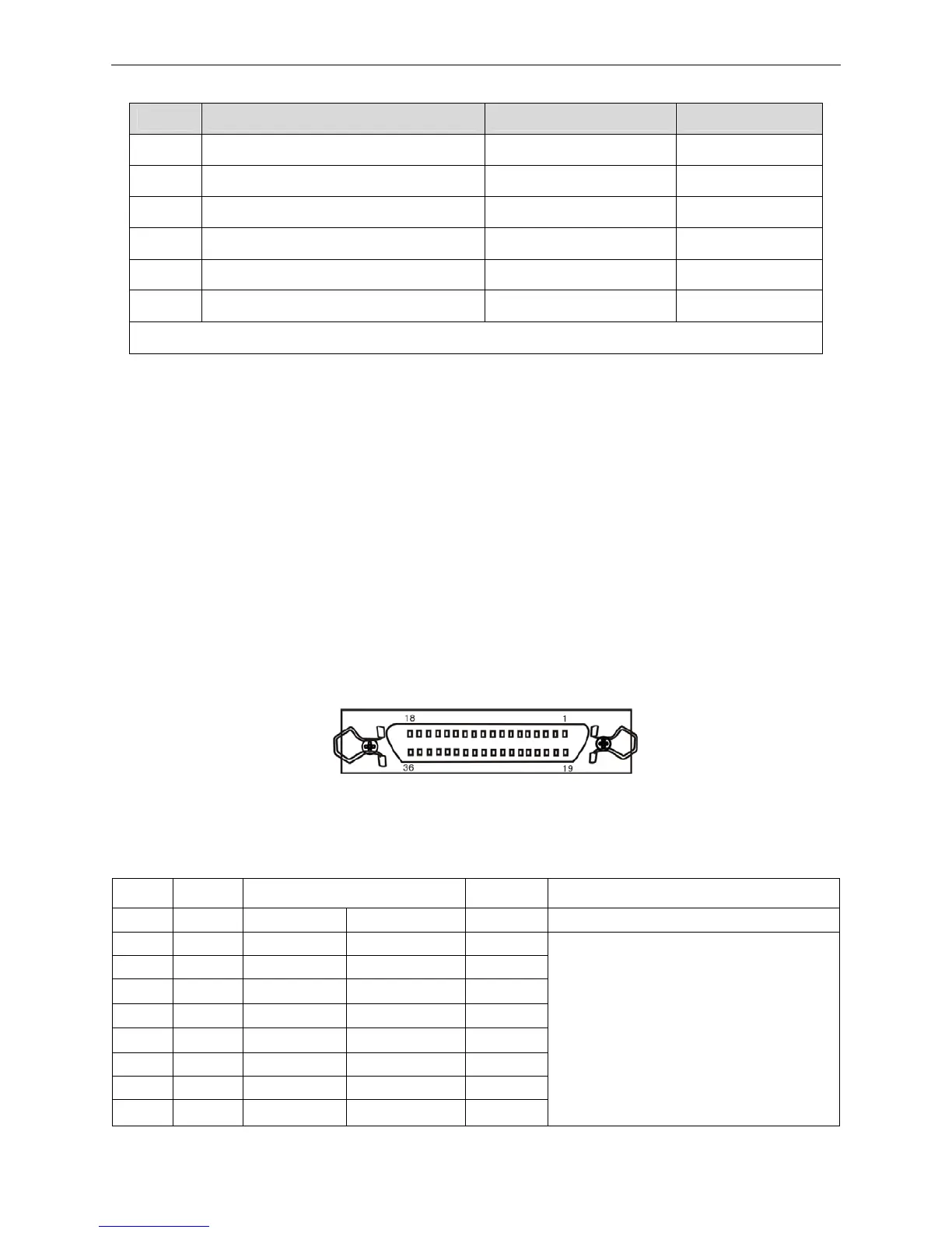
(2) Linker
Parallel interface is 57-30360 (AMPHENOL). The parallel interface connector is 36PIN type, shown
as Figure 5-2.
(3) Definition of pins (as shown in table A-2)
Table A-2 Pin function of parallel interface connector
Pin return Signal name Direction Description
1 19 /STROBE Data selected IN
Width of selected pulse is 0.5 µ sec.
2 20 DATA1 Date bit 1 IN / OUT
3 21 DATA2 Date bit 2 IN / OUT
4 22 DATA3 Date bit 3 IN / OUT
5 23 DATA4 Date bit 4 IN / OUT
6 24 DATA5 Date bit 5 IN / OUT
7 25 DATA6 Date bit 6 IN / OUT
8 26 DATA7 Date bit 7 IN / OUT
9 27 DATA8 Date bit 8 IN / OUT
Means 8 bits of parallel data signal. High
level means logical “1”, low level means
logical “0”.
Figure 5-2 Pins number of the parallel interface connector