20
3-4 Input Terminals
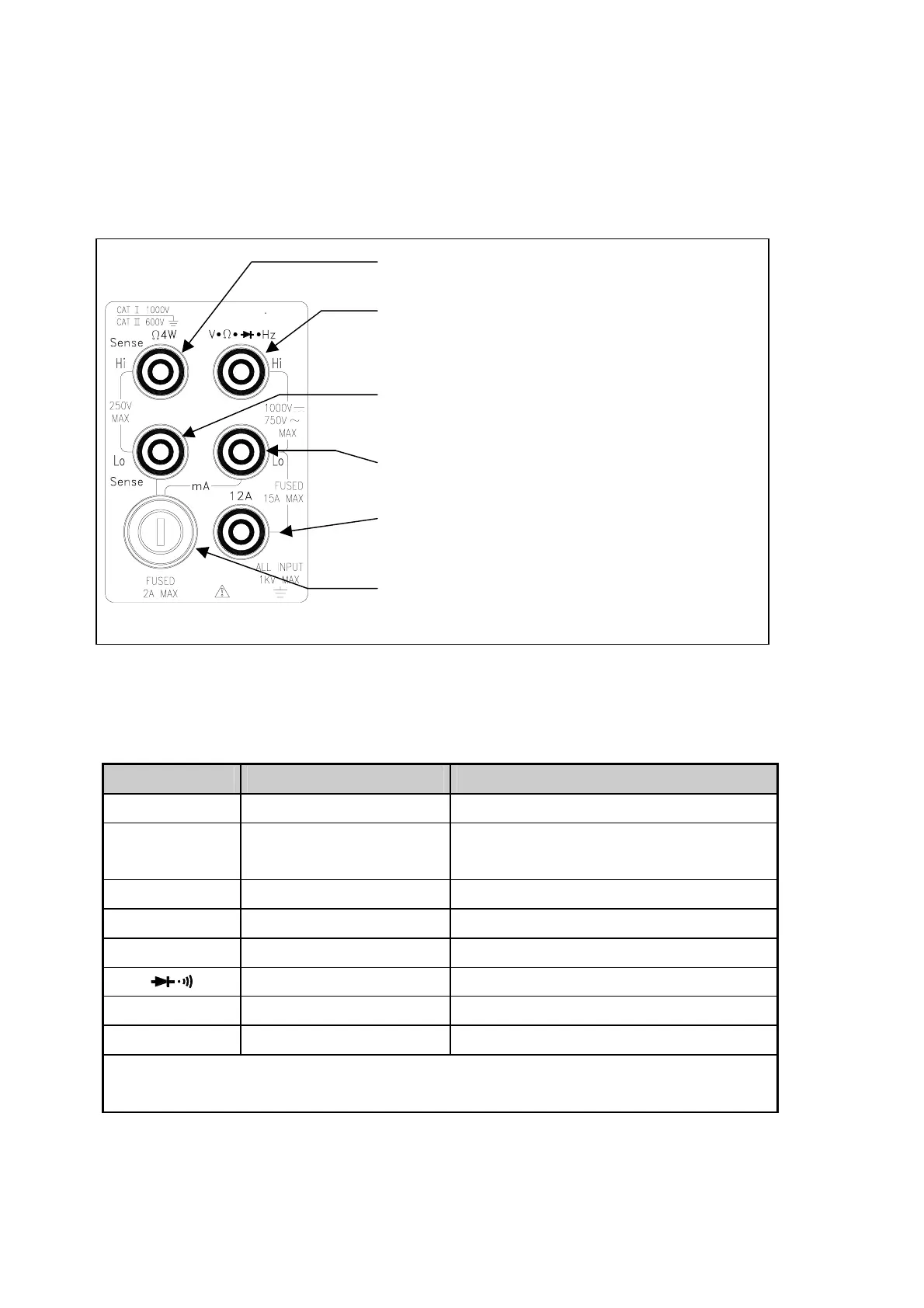
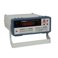
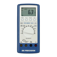
The input terminals, shown in Figure 3-2 are located on the left side of the front
panel. The meter is protected against overloads up to the limits shown in Table
3-1. Exceeding these limits poses a hazard to both the meter and operator.
Figure 3-2 Input Terminals
Table 3-1 Input Protection Limits
Function Input Terminal Maximum Allowable Input
Vdc
VΩ
ΩΩ
ΩHz (Hi) to Lo
1000V dc
Vac, Hz
V Ω
ΩΩ
Ω Hz (Hi) to Lo
750V ac rms, 1100V peak, 2x10
7
V-Hz
normal mode, or 1x10
6
V-Hz common mode
mA, Hz mA to Lo
1200mA
(1)
dc or ac rms
12A, Hz 12A to Lo
12A
(2)
dc or ac rms
Ω
ΩΩ
Ω (2W) VΩ
ΩΩ
ΩHz to Lo
500V dc or ac rms
VΩ
ΩΩ
ΩHz to Lo
500V dc or ac rms
Ω
ΩΩ
Ω (4W)
Sense Hi to Sense Lo 250V dc or ac rms
All functions Any terminal to earth 1000V dc or peak ac
(1)
Up to 1200mA for 5492; up to 120mA only for 5491
(2)
10A dc or ac rms continuous, and 12A dc or ac rms for 30 seconds maximum
!
Ohm (4W) Sense-High Terminal
!
Input-High Terminal for Volts, Ohms, Hz,
Diode/Continuity Measurements
!
12mA~1200mA Range DC/AC Current Input and
Ohm (4W) Sense-Low Terminal
!
Input-Low and Common Terminal (COM)
!
12A Range Current Input Terminal for 12A Range
DC/AC Current Measurement
!
12mA/120mA/1200mA mA Fuse & Holder (2A for 5492;
250mA for 5491)