Do you have a question about the BK Precision 5492B and is the answer not in the manual?
General safety information and warnings regarding instrument operation and installation.
Key safety precautions for both operating and maintenance personnel.
Explains the meaning of safety symbols used in the manual.
Details WEEE disposal and CE declarations for the product.
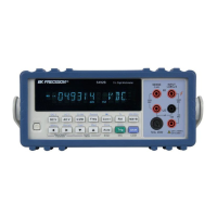
Describes the multimeter's main capabilities and measurement ranges.
Details power input voltage, frequency, and fuse specifications.
Lists all items included in the multimeter shipment.
Describes the front panel layout, controls, and important annunciators.
Explains the meaning of various icons and indicators on the display.
Details the measurement and math menu options available.
Explains the menu tree structure and how to navigate through it.
Describes the rear panel connectors and features.
Details connecting power and turning on the device safely.
Safety guidelines for measuring high-energy circuits.
Describes the factory default settings of the instrument.
Explains the time needed for stable and accurate measurements.
Introduces the front panel keys used for selecting measurement functions.
Details the procedure and connections for measuring voltage.
Details the procedure and connections for measuring current.
Instructions for replacing fuses located on the front panel.
Details the procedure and connections for measuring resistance.
Explains how to shield resistance measurements for accuracy.
Details the procedure for measuring frequency and period.
Details the procedure for performing continuity testing.
Describes how to define the continuity test threshold.
Details the procedure and connections for diode testing.
Explains how to set the test current for diode measurements.
Introduces the different math operations available on the multimeter.
Details the configuration and use of the mX+b math calculation.
Details the configuration and use of the percentage calculation.
Details the configuration and use of the dB calculation.
Details the configuration and use of the dBm calculation.
Covers instrument range settings and filter configuration.
Details how to set up and configure the digital filter.
Explains how to use the relative measurement feature.
Explains the effect of rate settings on integration time and noise.
Introduces the multimeter's triggering system capabilities.
Explains the instrument's trigger process flow.
Details how to set the trigger source for measurements.
Describes the configuration of programmable trigger delay.
Describes the functionality of external trigger and VM Comp BNC terminals.
Introduces the internal buffer for storing readings and statistics.
Procedure for storing readings into the internal buffer.
Procedure for recalling stored readings and their statistics.
Explains MAX, MIN, AVG, and STD statistical calculations for buffer data.
Introduces the limit testing feature and its functionality.
Details how to configure high and low limits for limit testing.
Describes how to configure beeper alerts for limit test conditions.
Overview of various system settings available on the multimeter.
Details how to enable or disable the beeper function.
Procedure for saving current instrument settings to memory.
How to restore saved or factory default settings.
How to turn the front panel display on or off.
Details how to enable or disable the key press sound.
Instructions on how to perform instrument self-test routines.
Information regarding instrument calibration procedures.
Overview of available remote communication interfaces (USB, RS-232, GPIB).
Details on setting up and using the USB interface.
Details on setting up and using the RS-232 serial interface.
Details on setting up and using the GPIB interface.
General information on operating with USB and RS-232 interfaces.
Pinout and cable requirements for RS-232 communication.
Data settings (bits, parity, termination) for USB/RS-232.
Procedure for setting the baud rate for communication.
Procedure for selecting the parity mode (None, Even, Odd).
Procedure for selecting terminal characters (LF, CR, LFCR).
How to enable or disable the echoing function for handshake.
Details on communication handshake protocols using software.
Describes GPIB system configuration restrictions for cable length and devices.
Lists the instrument's GPIB capabilities and functions.
Procedure for setting the instrument's GPIB address.
Describes the ASCII character string format for GPIB output.
Explains the hierarchical structure of SCPI commands.
Details command and parameter syntax, including brackets and angle brackets.
Rules for determining the short-form version of SCPI commands.
General rules for SCPI commands regarding case sensitivity and spacing.
Rules for executing multiple commands on a single line using semicolons.
Rules for navigating through SCPI command paths.
Lists the available subsystem commands.
Commands used to acquire measurement readings.
Details the MEASure SCPI command for one-time measurements.
Details the CONFigure SCPI command for setting measurement mode.
Details the FETCh SCPI command for obtaining the last reading.
Details the READ SCPI command for triggering and fetching a reading.
Commands used to control the front panel display.
Commands used to configure and control math calculations.
Commands used to configure and control buffer operations.
Action command to clear the readings stored in the buffer.
Command to specify the buffer size (number of readings to store).
Query command to retrieve stored buffer data.
Specify statistical calculations to recall from buffer data.
Enable or disable the store reading function for the buffer.
Commands used to configure and control the limit test.
Command to specify the upper limit for limit testing.
Command to specify the lower limit for limit testing.
Enable or disable the limit test function.
Read the results of the limit test (pass/fail).
Commands used to configure and control measurement functions.
Command to configure the current range for diode test.
Command to configure the threshold resistance for continuity test.
Selects the measurement function for the instrument.
Sets the integration rate (NPLC) for measurements.
Manually selects the measurement range for a function.
Controls the auto ranging feature for measurements.
Establishes reference values for relative measurements.
Enables or disables the reference mode.
Acquires the measurement input signal as the reference value.
Configures averaging filters for measurements.
Enables or disables the digital filter for averaging.
Selects the type of averaging filter (Moving or Repeat).
Specifies the filter count for averaging calculations.
Sets the voltage threshold for frequency and period measurements.
Miscellaneous system commands for instrument configuration.
Returns the instrument to its factory default settings.
Enables or disables the autozero function.
Enables or disables the beeper function for tests.
Restores front panel operation from remote mode.
Configures measurement units for ACV and DCV.
Commands to configure the trigger model for measurements.
Initiates a single trigger cycle.
Enables or disables continuous initiation of triggers.
Aborts the current instrument operation.
Configures trigger mode and trigger delay.
Selects the trigger source (IMMediate, BUS, MANual, EXTernal).
Sets the trigger delay time in milliseconds.
Enables or disables auto trigger delay.
Describes common SCPI commands like *RST, *TRG, and *IDN?.
Answers common questions related to front panel and remote operation.
Lists and describes common error codes encountered during operation.
General specifications, assumptions, and reading rates.
Detailed specifications for DC voltage measurements.
Detailed specifications for DC current measurements.
Detailed specifications for AC voltage measurements.
Detailed specifications for AC current measurements.
Detailed specifications for resistance measurements.
Specifications related to the continuity test function.
Specifications related to the diode test function.
Specifications for frequency and period measurements.
Lists the standard programming languages supported.
Supported remote interfaces (GPIB, USB, RS-232).
Environmental, power, dimensions, and weight specifications.
Details the process for obtaining warranty service.
Details the process for obtaining non-warranty service.
Outlines the terms and conditions of the three-year warranty.
| Model | 5492B |
|---|---|
| Category | Multimeter |
| Manufacturer | BK Precision |
| Display Type | LCD |
| Temperature Measurement | Yes |
| Continuity Test | Yes |
| Diode Test | Yes |
| Data Logging | Yes |
| Interface | USB |
| Data Hold | Yes |
| Auto Power Off | Yes |
| Power Supply | 9V battery |
| Frequency Range | 10Hz to 10MHz |
| Temperature Range | -40°C to 1000°C |