Basic Measurements
26
3.4 Measuring Resistance
Resistance measurement range: 120 Ω, 1.2 kΩ, 12 kΩ, 120 kΩ, 1.2 MΩ, 12 MΩ, 120 MΩ
Maximum resolution: 1 mΩ (on 120 Ω range)
3.4.1 Connections
Assuming the multimeter is under factory default conditions, the basic procedure for measuring
resistance is as follows:
1. Connect test leads to the multimeter as follows:
A: For Ω2-wire, connect the test leads to INPUT HI and LO.
B: For Ω4-wire, connect the test leads to INPUT HI and LO, and SENSE Ω 4W HI and LO. Kelvin
test probes are recommended for this setup.
2. Select Ω 2-wire or Ω 4-wire measurement function by pressing or →
respectively.
3. Press to toggle between auto and manual ranging. Notice the AUTO annunciator is
displayed with auto ranging. For manual range, use the RANGE and keys to select a
measurement range.
4. Connect test leads to the resistance as shown in Figure 3-3:
CAUTION: Do not apply more than 1000 V peak between INPUT HI and LO or it will damage the
instrument
5. If the “OVR.FLW” message is displayed, press up key to select a higher range until a normal
reading is displayed (or press key for auto ranging). Use the lowest possible range for the
best resolution.
6. The measured reading is displayed.
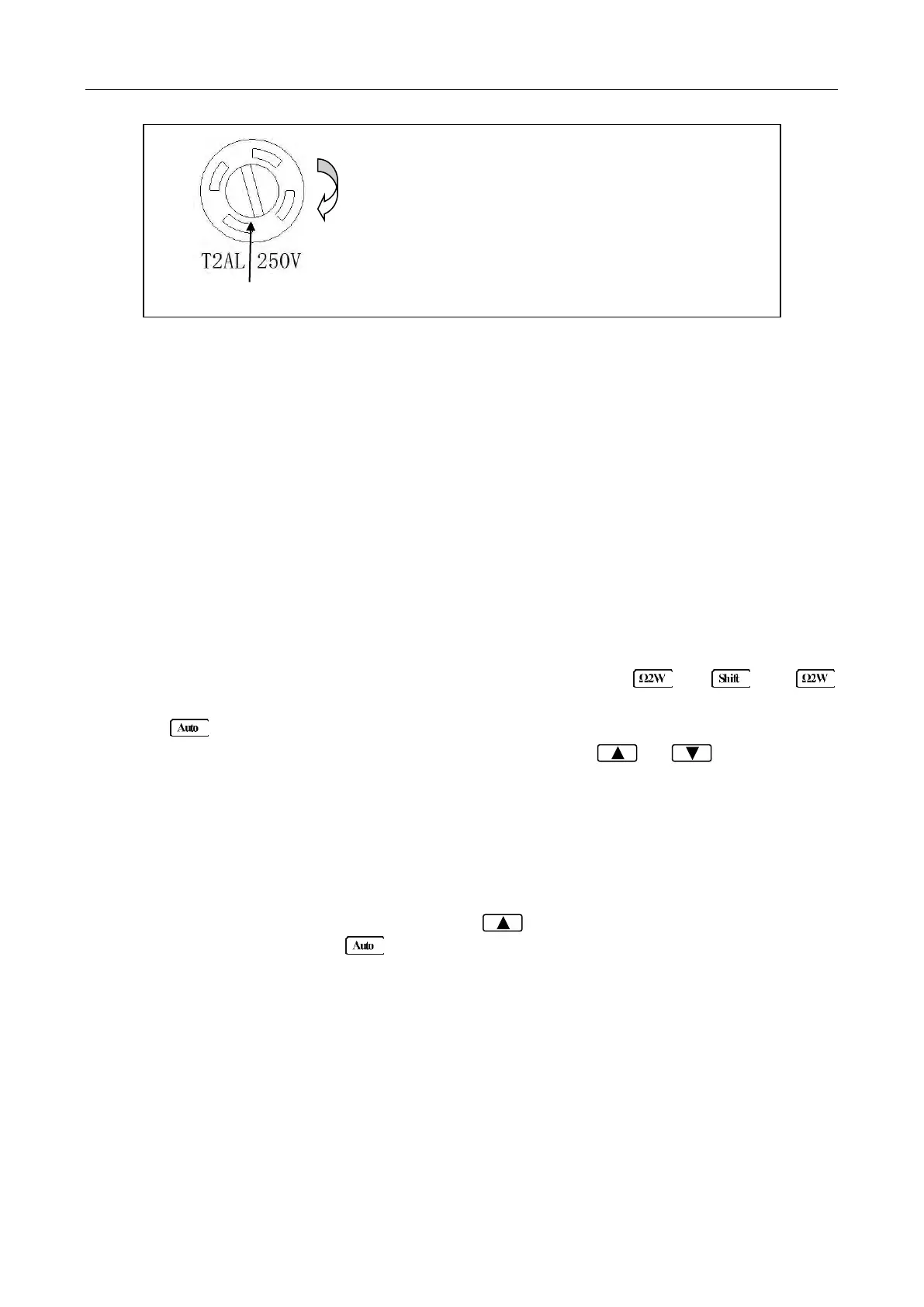
To remove, use a flat head screw driver or a coin to
insert into the slid and turn counter-clockwise to
open. Similarly to put back the fuse box, push the
box down and turn clockwise.
www.GlobalTestSupply.com
Find Quality Products Online at: sales@GlobalTestSupply.com