Basic Measurements
29
T2AL 250V
SENSE
Ω4W
VΩ
LO
HI
!
10A
CATⅡ(300V)
CATⅠ(1000V)
350V
MAX
1000V
MAX
12A
MAX
mA
12A
INPUT
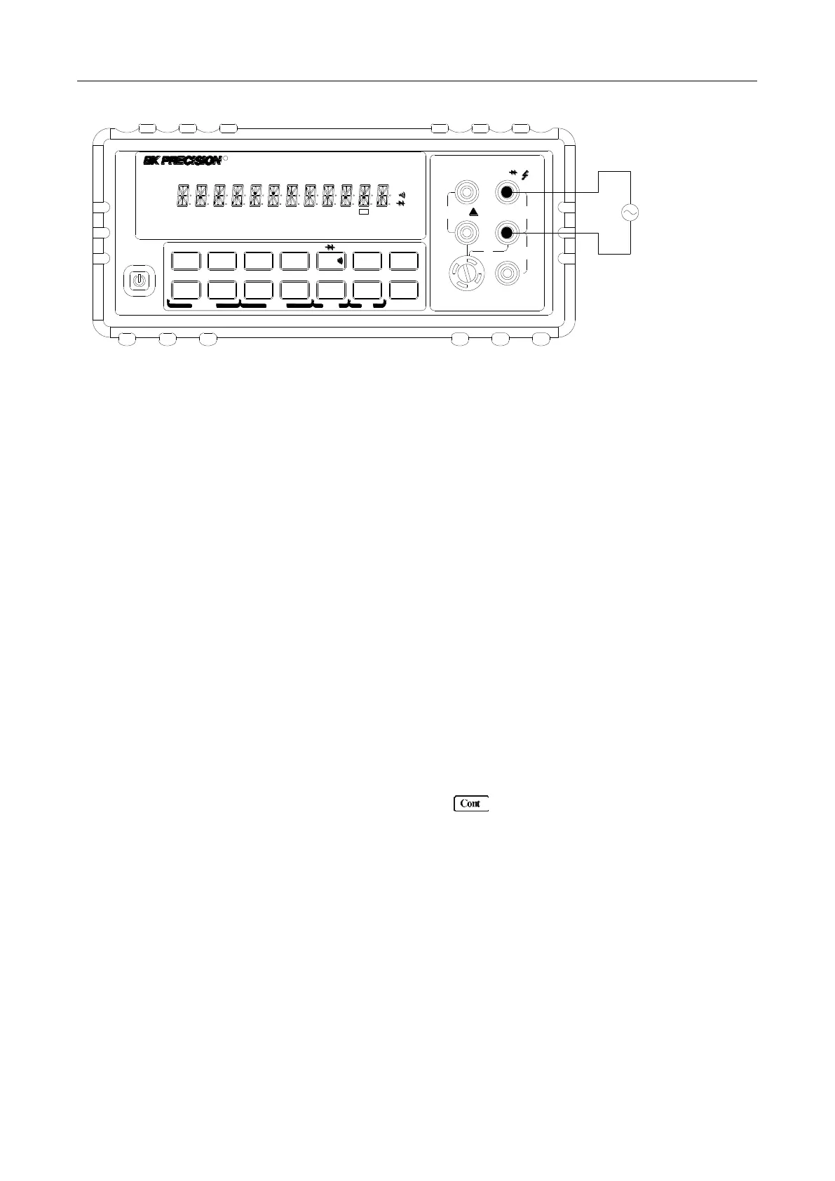
AC Voltage
Source
▲
▲
▲
▲
DC V AC V 2W Freq
Aut o
Tr i g
MX+B
Shi f t
Cont Rel
¦¸
Period
dB/m
FastMenu Recall Med Slow Hold
CHOICES
LEVEL ENTER
ESC
LOCAL
%
IDC IAC 4W
Ω
FAST
MED
SLOW
ADRS RMT HOLD TRIG
*
MEM AUTO REL FILT MATH SHIFT
4W
ERR
POWER
R
5
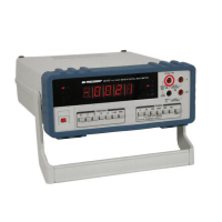
5492B
1
2
/
Digit Mult imeter
Input Impedance = 1 MΩ in parallel with <100 pF
CAUTION: Maximum Input = 750 RMS, or 1000 V Peak
Figure 3-4 Frequency and Period Measurements
3.6 Measuring Continuity
The multimeter uses the 1 kΩ range to measure circuit continuity. A threshold resistance level (1 Ω to
1000 Ω) should be set. The factory default value is 10 Ω. The multimeter alerts you with a beep when a
reading is below the set level.
Note: Continuity function defaults to FAST (0.1 PLC) rate and cannot be changed.
3.6.1 Connections
Assuming the multimeter is under factory default conditions, the basic procedure for continuity testing is
as follows:
1. Connect test leads to the INPUT HI and LO terminals.
2. Select Continuity measurement function by pressing .
3. Connect test leads to the resistance under test as shown in Figure 3-5.
4. The measured reading is displayed.
www.GlobalTestSupply.com
Find Quality Products Online at: sales@GlobalTestSupply.com