Remote Operation
56
5.2 USB & RS-232 Interface Operation
5.2.1 RS-232 Connection
The RS-232 interface on this instrument uses a 9-pin DB9 connector. The pin outs are defined below in
Table 5-1:
Table 5-1 RS-232 Pin Out
9 Pin Connector Pin Number
Figure 5-1 shows the rear panel connector for the RS232 interface.
Figure 5-1 Rear Panel RS232 Interface
Note: To interface with a serial port on a computer with the RS232 interface, use a NULL
MODEM or CROSS OVER serial DB-9 female to female cable. Do NOT use a straight-through
serial DB-9 cable. To check that you have the correct cable, probe pin 2 on one end and pin 3 on
the other and vice versa to check continuity.
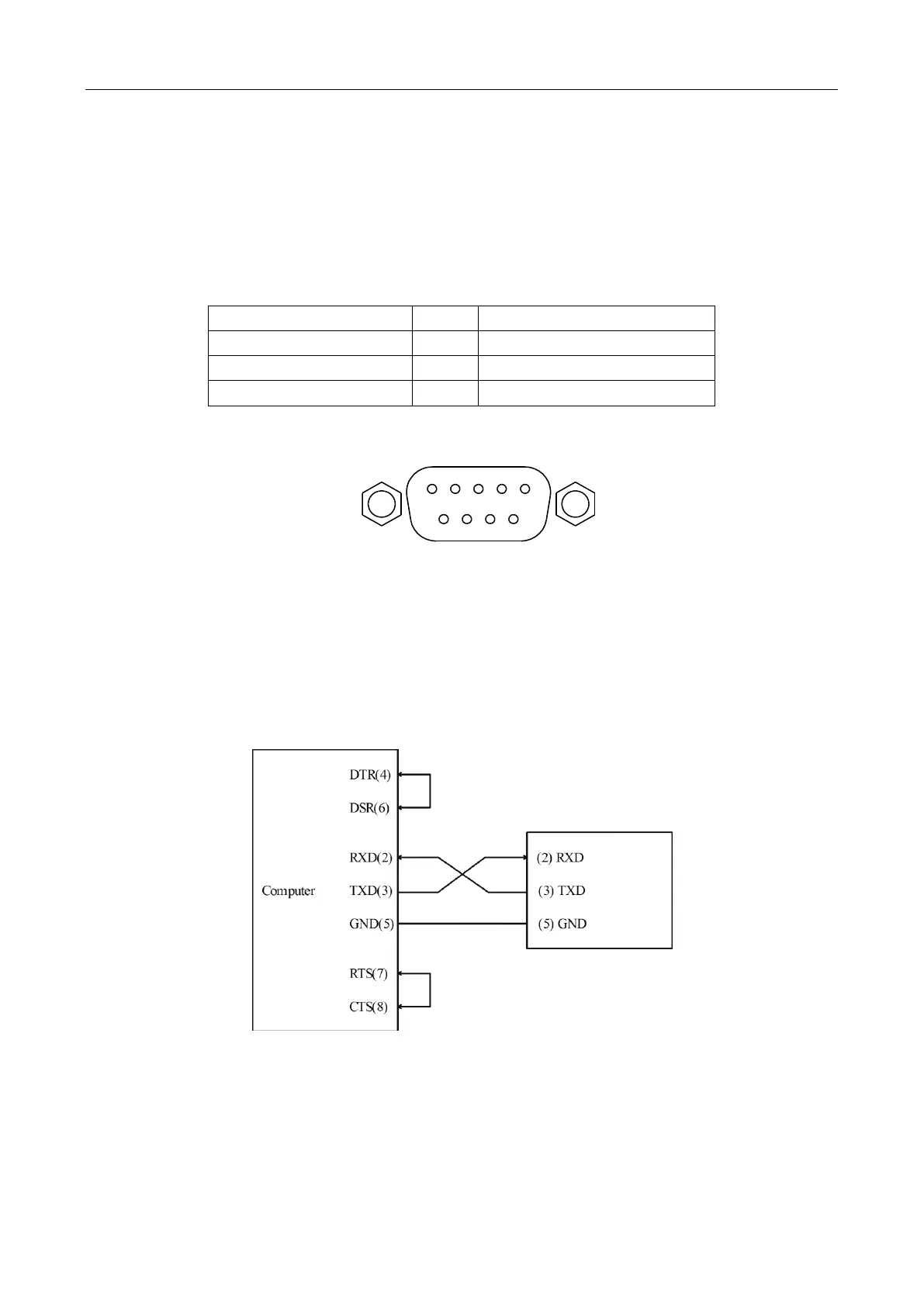
Below is a pin connection diagram between 5492B and a computer (Figure 5-2):
Figure 5-2 RS-232 Connection Sketch
Note: Pin 4 and 6, pin 7 and 8 are shorted respectively at the end of the controller.
www.GlobalTestSupply.com
Find Quality Products Online at: sales@GlobalTestSupply.com