Basic Measurements
30
T2AL 250V
SENSE
Ω4W
VΩ
LO
HI
!
10A
CATⅡ(300V)
CATⅠ(1000V)
350V
MAX
1000V
MAX
12A
MAX
mA
12A
INPUT
Resistance
Under Test
▲
▲
▲
▲
DC V AC V 2W Fr eq
Aut o
Tr i g
MX+B
Shi f t
Cont Rel
¦¸
Period
dB/m
FastMenu Recall Med Slow Hold
CHOICES
LEVEL
ENTER
ESC
LOCAL
%
IDC IAC 4W
Ω
FAST
MED
SLOW
ADRS RMT HOLD TRIG
*
MEM AUTO REL FILT MATH SHIFT
4W
ERR
POWER
R
5
5492B
1
2
/
Dig it Multimet er
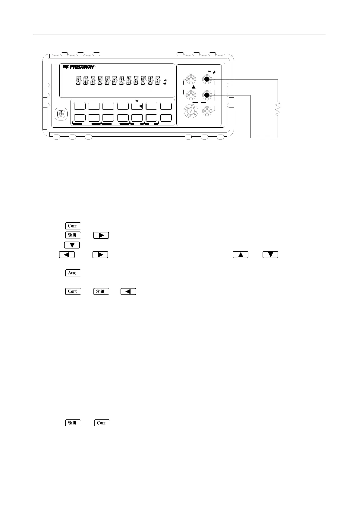
Note: Source current flows from the INPUT HI to INPUT LO terminals.
Figure 3-5 Continuity Measurement
3.6.2 Threshold resistance level
You can define a threshold resistance from 1 Ω to 1000 Ω. Factory default value is 10 Ω. Follow the steps
below to define the resistance level:
1. Press for Continuity Measurement.
2. Press → to enter the submenu level, “1: CONTINUITY” will be displayed.
3. Press to enter the parameter level, the current LEVEL value will be displayed.
4. Use and keys to change the cursor position and use and keys to
increment or decrement the digits respectively. Enter a value from 1 to 1000.
5. Press (ENTER) to confirm your setting. Message “CHANGE SAVED” will be displayed for a
moment.
6. Press or → to exit the menu and return to the continuity measurement.
3.7 Testing Diode
The multimeter can also be used to measure the forward voltage drop of general-purpose diodes and
zener diodes. A current range (1 mA, 100 μA, or 10 μA) can be selected for diode measurement.
Note: Diode testing defaults to MED (1 PLC) rate and cannot be changed.
3.7.1 Connections
Assuming the multimeter is under factory default conditions, the basic procedure for diode testing is as
follows:
1. Connect test leads to INPUT HI and LO terminals.
2. Press → for diode measurement function.
3. Connect test leads to the diode under test as shown in Figure 3-6.
4. Take a reading from the display.
www.GlobalTestSupply.com
Find Quality Products Online at: sales@GlobalTestSupply.com