11
! Voltage, Resistance or Frequency Measurements
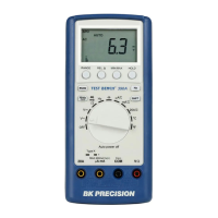
Press the desired function button and connect the test leads (TL 36 or TL 35
as described in Section 1-3) as shown in Figure 2-5 to measure voltage,
resistance, or frequency. The meter will select the appropriate range in the
auto-range mode, and an annunciator on the display will indicate
measurement units.
NOTE
Excessive error may occur when making measurements with 1 to 10
µ
V
resolutions after measuring high voltage up to 1000 volts dc. It requires two
minutes before making low-level measurements.
! Current Measurements
To measure current, connect the test leads to mA input terminal or 12A input
terminal for measured current above 1200mA (5492) / 120mA (5491) as
shown in Figure 2-6.
Be sure to turn off the power in the circuit to be measured before taking
current measurement.
Break the circuit on the groundside to minimize the common mode voltage)
to be measured, and place the meter in series at that point.
Turn on power to the circuit, and then read the display. The meter will select
the appropriate range automatically, and an annunciator on the display will
indicate the units of the measurement value shown.
Turn off power to the circuit and disconnect the meter from the tested circuit.
NOTE
After making a high current measurement using the 12A input, thermal
voltages are generated that may create errors when making high-resolution
low-level dc measurements of volts, amps, or ohms.
It requires ten minutes to allow the thermals to settle out before making
low-level measurements in order to obtain the best accuracy.