30
Setup Tolerance Mode
1. Select the primary measurement mode based on the type of components to be
measured. This is done by pressing the button to configure the desired
measurement mode.
Note: Be sure to select the correct measurement mode, as tolerance mode cannot be
activated unless the correct mode is selected. For example, if the component is a
capacitor, be sure to select “C” for capacitance. If not, tolerance mode will not be
activated following the proceeding steps below.
2. Configure the proper test frequency and series/parallel equivalent mode.
3. Perform the operation of calibration (CAL) if necessary.
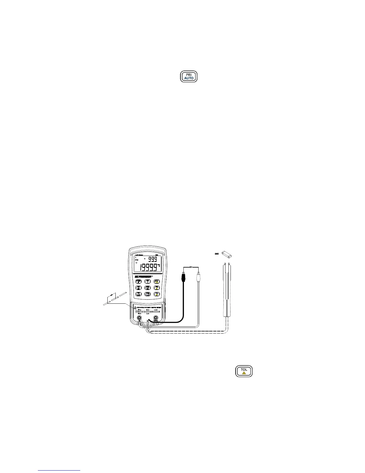
4. Insert a known “good” component that will be used for testing against all other
components.
This component will be the “standard” reference value
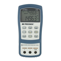
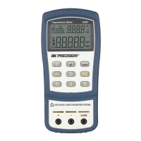
(See Figure 9 for illustration)
Note: The tolerance mode cannot be activated unless the meter senses a component is
connected to either the input sockets or terminals.
Figure 9 - Inserting Components to Inputs
5. Once the desired measured reading is displayed, press the button once to store
the reading as the “standard” value or test reference value. At this point, the “TOL” will
be displayed on the screen, indicating that the tolerance mode is activated.
Note: Any value which appears on the LCD display, such as DH (data hold) or
MAX/MIN/AVG, can also be used as the “standard” value or test reference value for
sorting components.