18
9803 and 9805
The 9803 and 9805 has a rear AC output terminal that is also isolated from the AC power input
of the instrument. The connector is protected by an AC output terminal cover. Please follow the
steps below to make a secure connection to the output terminal.
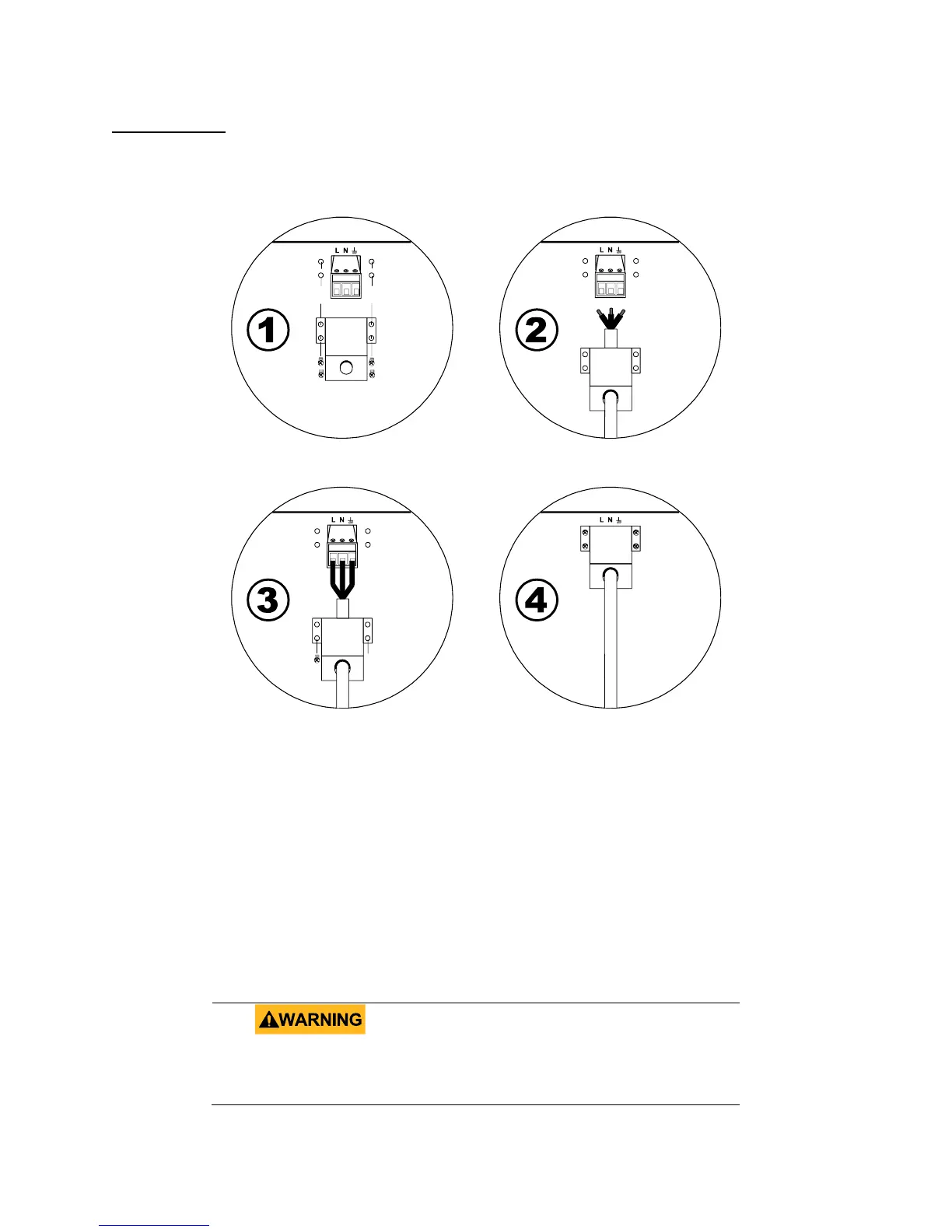
Step 1: Remove the screws attached to the AC output terminal cover.
Step 2: Slide the wires (not supplied) through the hole of the AC output terminal cover. Note:
Refer to Table 2 - Wire Gauge Rating to determine the type of wires to use.
Step 3: Place the three wire ends through the output terminal. Make note of the wires and
ensure the proper color wire is connected to the right terminal. (i.e. In the US, Green/yellow-
green is Ground, White is Neutral (N), and Black is Line/Hot (L)). Tighten down the wires so
they are secured to the output terminal block.
Step 4: Place the AC output terminal cover over and secure it to the rear panel of the
instrument by fastening the four screws on the sides of the cover.
Before connecting wires to the output terminals, turn
OFF the power supply to avoid damage to the
instrument and the device under test (DUT). For
Figure 21 - Rear Panel Terminal Block Connection