JUST POWER ON90
3.6 Connect the grid and load cable
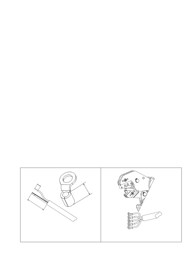
Step 1 : Select the appropriate cable type and specification according to figure
6-3; Strip the cable, For the stripping length, refer to figure 6-5-1.
Step 2 : Insert the wire core with the insulation layer stripped into the conductor
crimping area of OT terminal, and press it with crimping pliers(Figure 6-5-2).
Step 3 : Connect the cable with crimped terminals according to the electrical
polarity of the load symbols marked on the junction box, and fasten with a
screwdriver(6-5-3).
Step 4 : Connect the cable with crimped terminals according to the electrical
polarity of the grid symbols marked on the junction box, and fasten with a
screwdriver(Figure 6-5-4).
Step 5 : Put the PG waterproof connector into the AC protective cover of junction
box , and tighten the hexagonal nut on the bottom of the PG waterproof connec-
tor with a socket tool( Figure 6-5-5).
Step 6 : Pass the cable through the PG waterproof connector , then fix the
protective cover to the junction box with 6Pcs M4 screws. Tighten the screws with
a cross screwdriver(Figure 6-5-6).
Step 7 : Tighten the nut outside the PG waterproof joint clockwise(Figure 6-5-7).
A=55~65mm
B=C+3mm
Figure 3-6-1 Figure 3-6-2
A
B
C
 Loading...