OZONE ANALYZER BMT 965 Manual, Rev. 01/2024
___________________________________________________________________________
12
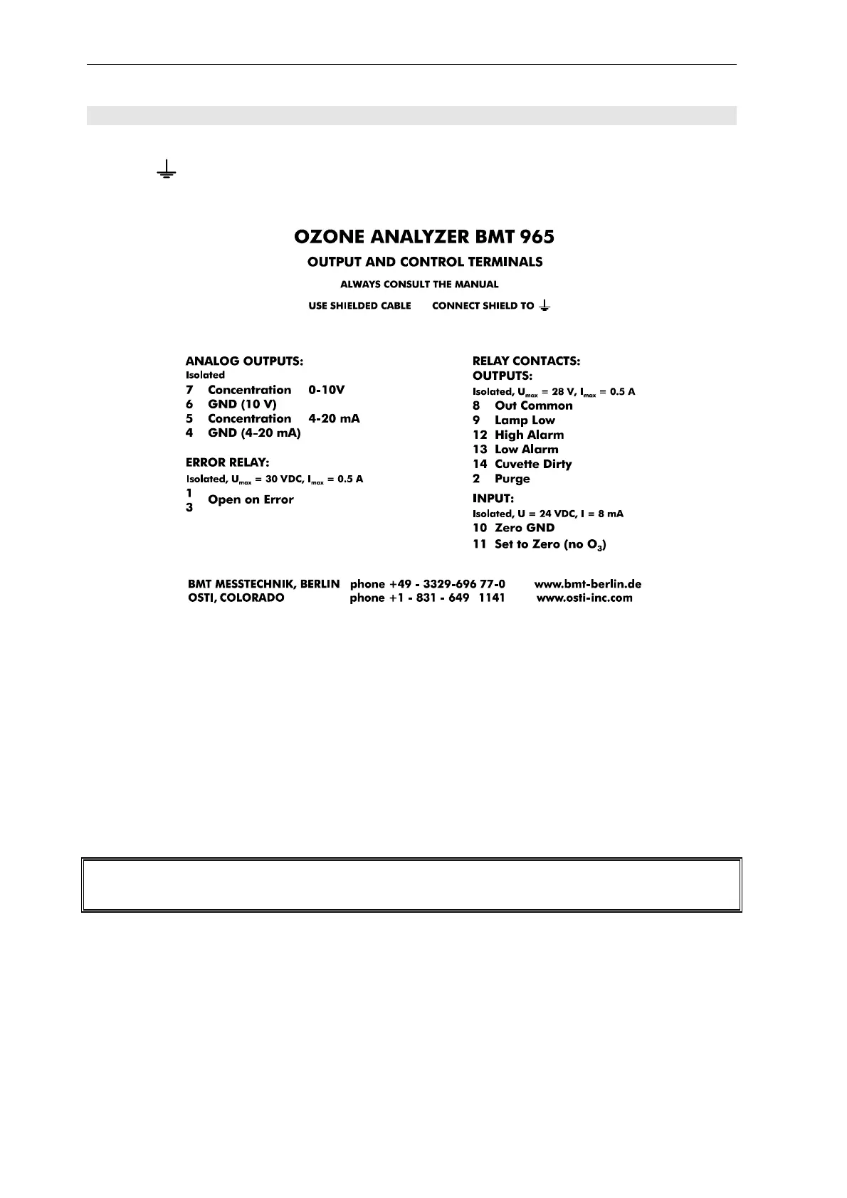
4 Output and Control Terminals
The signal cable should be shielded. The shield should be connected to the protective ground
terminal ( ) of the instrument via an 1/4'' FASTON connector. The following table describes
the pinout of the signal connector. This is also printed onto the top of the standard instruments:
Analog Outputs
The output signals are updated about 10 times per second.
The voltage output is an isolated voltage signal 0 to 10 V, proportional to the concentration (actu-
ally this signal swings down to about -0.25 V below zero). Input resistance of the load should be
higher than 1 k.
The current output is an isolated current signal 4 to 20 mA, proportional to concentration (with an
offset of 4 mA). Input resistance of the load should be less than 600 . The current output pro-
vides the energy for the current loop.
Warning: The current output (4-20 mA) is an active analog signal transmitter. It must not be con-
nected to an active receiver or power supply!
Binary Input
The binary input is a control input used to trigger the ZERO function of the
OZONE ANALYZER BMT 965. By applying a voltage of typically +24 VDC between pin 11 (+)
and pin 10 (-) for about 0.5 seconds the instrument will be zeroed. The ZERO function may be
triggered only after complete purging of the cuvette with filtered air or oxygen (purging for
at least 10 seconds plus delay of the input tubing)!