OZONE ANALYZER BMT 965 Manual, Rev. 01/2024
___________________________________________________________________________
63
The REMOTE DISPLAY is connected to its own 12-pole connector. The 16-pole Signal Con-
nector is free for access to all signal inputs and outputs. The analyser must be ordered as
BMT 965 AQ/RD in order to operate together with a REMOTE DISPLAY.
For further description of the functions and properties of the OZONE-IN-WATER SENSOR
BMT 965 AQ refer to the main part of the manual.
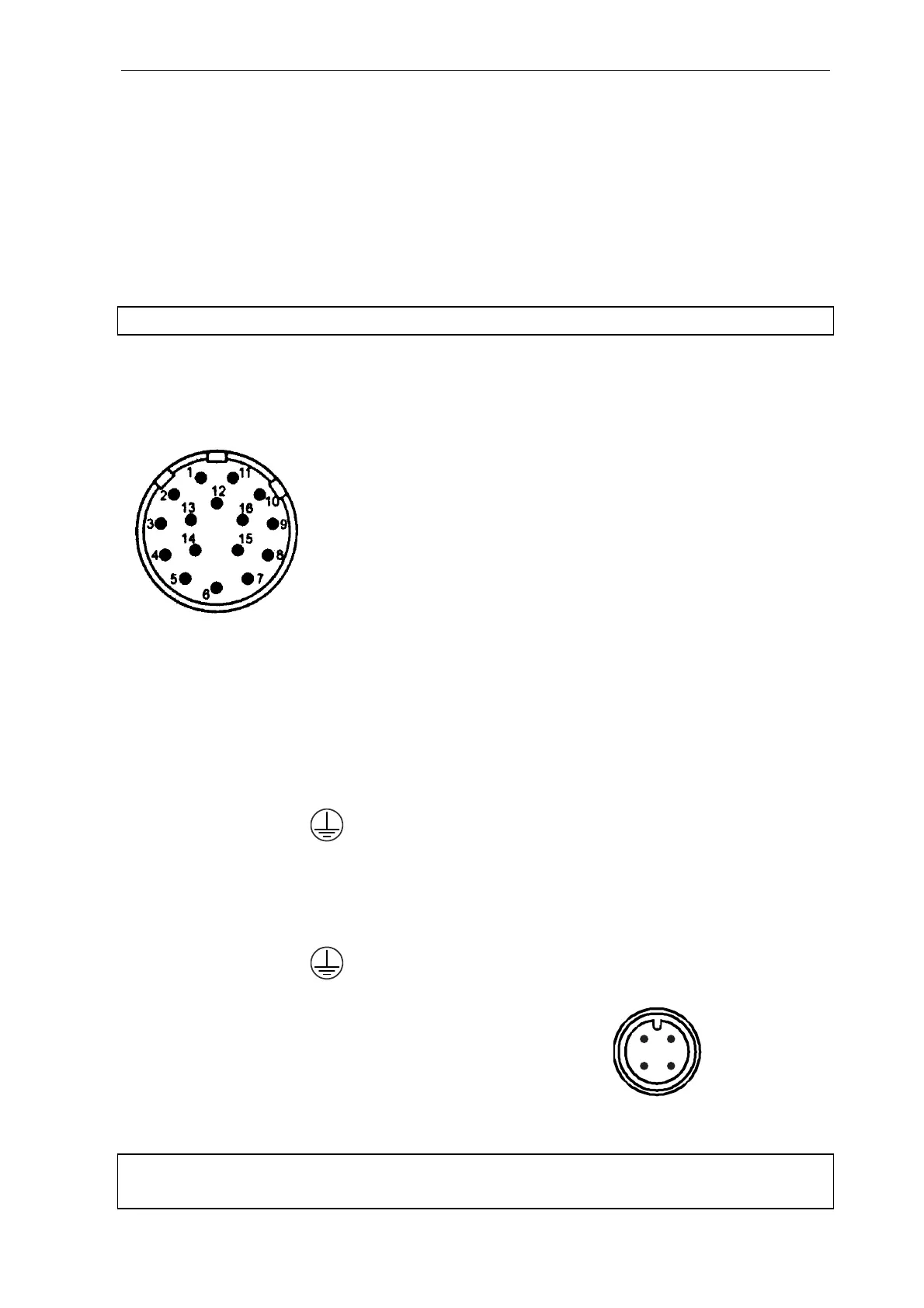
Electric connections
Note: The signal connector pinout of the BMT 965 AQ is different to the that of the BMT 965 ST!
Signal connector: 1 current signal, output 4 - 20 mA high
2 current signal, output 4 - 20 mA low
3 voltage signal, output 0 - 10 V high
4 voltage signal, output 0 - 10 V low
5 Auto Zero, input high (+24 VDC, 18mA)
6 Auto Zero, input low
7 Error Contact, output
} open on error
8 Error Contact, output
9 Purge Control, output for external pump / solenoid valve
10 Output contacts, Common for pins 9, 12, 13, 14, 15
11 Cable Shield
12 Lamp Low, output open on error
13 Low Limit Alarm, output opening or closing
(conn. soldering side) 14 High Limit Alarm, output opening or closing
15 Cuvette Dirty, output open on error
16 not connected
Mains connector: 1 mains
} (100 bis 240 VAC, 50/60 Hz, 15 VA)
2 mains
3 (free)
Protective Ground
Alternatively:
DC power connector: 1 positive
} (12-36 VDC)
2 negative
3 (free)
Protective Ground
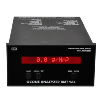
RS-232 connector: 1 Cable Shield
2 TxD (from BMT 965 AQ)
3 RxD (to BMT 965 AQ) (screw terminal
4 Signal Ground side)
Remote Display: 12-pole connector, only to be connected to BMT Remote Display
Note: The 24V DC version of the BMT 965 AQ is based on the same type of power connector,
but with the female connector on the SENSOR side.
2
1
3
4