OZONE ANALYZER BMT 965 Manual, Rev. 01/2024
___________________________________________________________________________
49
Caution: If the generator feed gas contains nitrogen, connect a tube to the outlet of the ozone
destruct to lead away the vent gas. Corrosive nitric acid will be formed when vent gas comes in
contact with the moist ambient air.
We strongly recommend to lead away the gas exiting the catalytic ozone destruct using PTFE or
FEP tubing 1/4" x 5/32"(or 4x6 mm). The Catalyzing Cartridge CAT-35 (left side of the cabinet)
has an outlet bore hole with female thread G 1/8 which normally is equipped with a fitting for this
kind of tubing. Other types of fitting can be delivered on request or be screwed into the G 1/8
thread by the user.
Caution: In case the ozone generator is serviced or repaired it is imperative that the ozone analyser
is disconnected (the sample gas flow is interrupted). We recommend the installation of a stop cock
or shut-off valve for this purpose.
We recommend replacement of the catalyst material in the Catalyzing Cartridge once per year in
case the oxygen feed gas contains a significant amount of nitrogen or other gases (e.g. PSA oxygen,
or oxygen with nitrogen doping). For replacement order "REFILL-35".
Electric connections
Warning: The cables shall only be connected by a person acquainted with the safety
requirements involved.
Warning: This product relies on the building's installation for short-circuit (overcurrent) protec-
tion. Ensure that a fuse or circuit breaker no larger than 15 A at 120 VAC (10 A at 240 VAC) is
used on the phase conductor.
Do not operate at an elevation higher than 2000 m.
An easily accessible means for switching off power should be provided. This disconnect has to be
clearly marked for identification of the instrument. Wire cross section of the power cable shall be
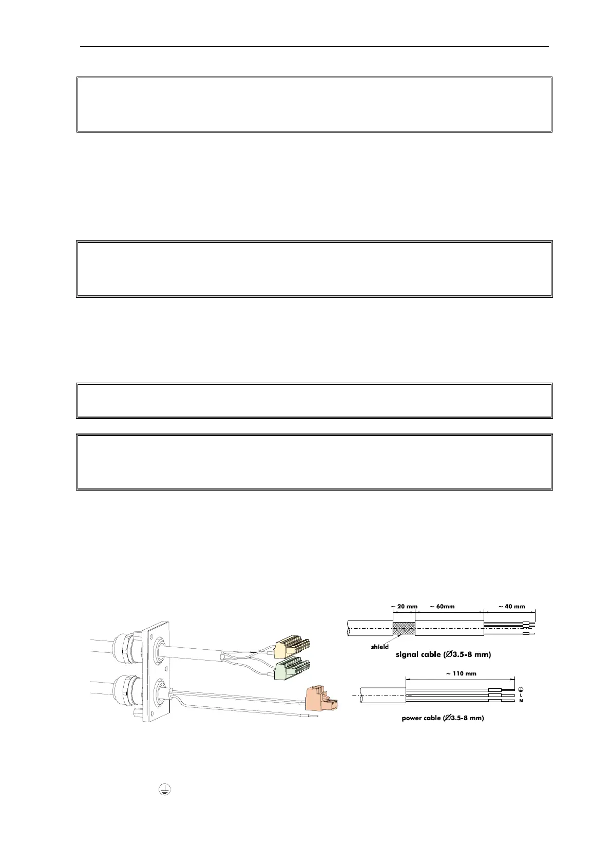
between 1.5 mm² and 4 mm² (AWG 16 to AWG 12). Use copper conductors only. The power
cable enters the cabinet through a water proof cable gland.
Connect the power carrying wires to the orange two pole female plug labeled "L" and "N" which
is provided with the instrument. Attach these wires to each other with a cable tie tightly behind the
orange two pole female plug. Connect the protective ground wire (PE) of the cable to the protective
ground terminal . Plug the orange two pole female plug with the power carrying wires into the