OZONE ANALYZER BMT 965 Manual, Rev. 01/2024
___________________________________________________________________________
50
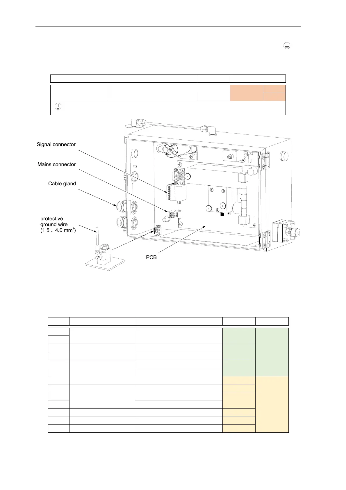
orange two pole connector on the PCB. Give enough slack on the PE (Protective Ground ) to
ensure that, if the strain relief of the cable gland should fail, the power carrying wires are
disconnected first.
mains, "N"
100 to 240 VAC, 50/60 Hz, 35 VA
input orange right
mains, "L" input left
Protective Ground
yellow-green wire,
to be connected to chassis grounding terminal inside Cabinet
The signal cable enters the cabinet through a water proof cable gland. It is held by a grounded cable
clamp which should have electrical contact to the cable shield. The different wires connect to the
two green and yellow PCB connectors, which are plugged into the two-row terminal block.
Connection:
1 Error contact Opening on any error output
green
3
4 Current output 4- 20 mA low output
5 4- 20 mA high
6 Voltage output 0- 10 V low output
7 0- 10 V high
8 Common for output contacts output
yellow
9 Lamp Low contact Opening on warning and error output
10 Auto Zero input Low (+24 VDC, 8 mA) input
11 High (+24 VDC, 8 mA)
12 High Alarm contact Opening or closing (selectable) output
13 Low Alarm contact Opening or closing (selectable) output
14 Cuvette Dirty contact Open on warning and error output