EasyManuals Logo

BobsCNC QUANTUM MAX User Manual

Default Icon
176 pages
To Next Page IconTo Next Page
To Previous Page IconTo Previous Page
Page #115 background imageLoading...
Page #115 background image
114
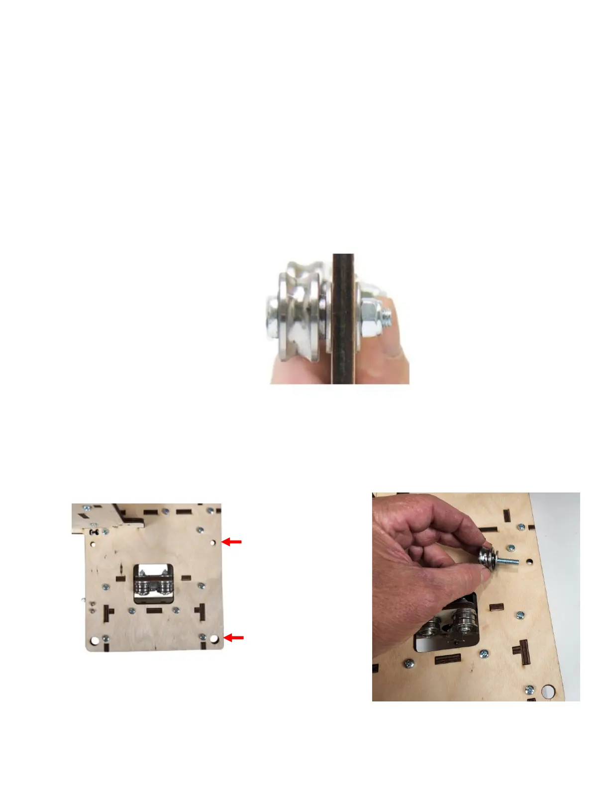
Step 5 Install the two Upper SG20U Bearing Assemblies for
the Gantry Side Frame Assembly. The assembly
order for the Upper Bearing Mounts: M6 x 35
Machine Screw (H95), SG20U Bearing (H44) (with
hub facing toward the Bearing Fender Washer),
Bearing Fender Washer (H42), Plywood, Bearing
Fender Washer (H42) secured with a M6 Lock Nut
(H18) as shown.
Step 6 Attach the upper SG20U Bearing Assembly to each
of the Gantry Side Assemblies
UPPER
BEARINGS
LOWER BEARINGS
(With Eccentric
Spacers)

Questions and Answers:

Question and Answer IconNeed help?

Do you have a question about the BobsCNC QUANTUM MAX and is the answer not in the manual?

BobsCNC QUANTUM MAX Specifications

General IconGeneral
BrandBobsCNC
ModelQUANTUM MAX
CategoryControl Systems
LanguageEnglish

Related product manuals