EasyManuals Logo

BobsCNC QUANTUM MAX User Manual

Default Icon
176 pages
To Next Page IconTo Next Page
To Previous Page IconTo Previous Page
Page #29 background imageLoading...
Page #29 background image
28
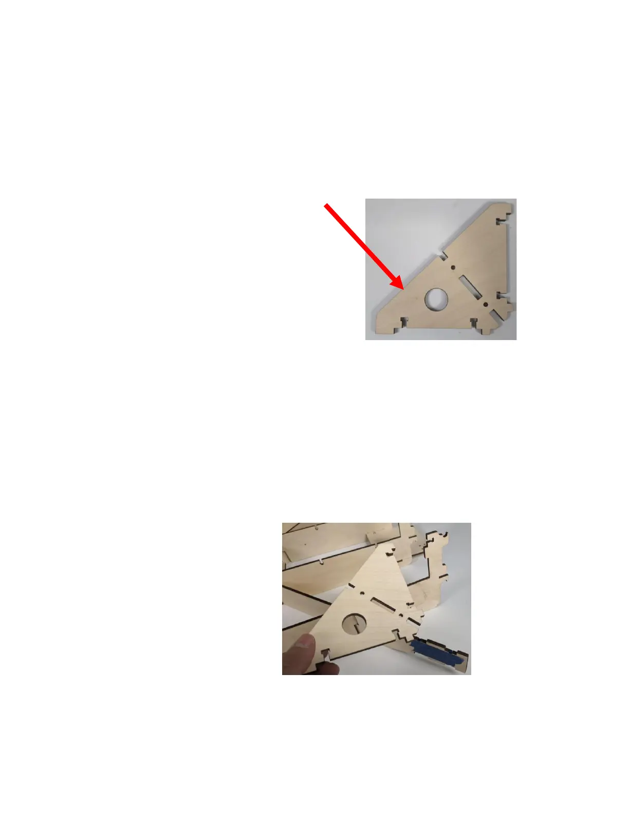
Step 7 Attach two Frame Corner Supports (QX8) on
the Torsion Arms (QX2). Note the circular
cutout in the Frame Corner Support can only
be installed facing toward the front or back of
the X Frame Assembly. In the Quantum Max, it
is oriented to rear.
Step 7a Align the slots in the Frame Corner Supports
(QX8) with the tabs on the Torsion Arms
(QX2). Slide in place and secure with two M4
x 16 Machine Screws. (The M4 Nuts were
previously installed and held in place with
blue painter’s tape). Repeat for each of the
corners.

Questions and Answers:

Question and Answer IconNeed help?

Do you have a question about the BobsCNC QUANTUM MAX and is the answer not in the manual?

BobsCNC QUANTUM MAX Specifications

General IconGeneral
BrandBobsCNC
ModelQUANTUM MAX
CategoryControl Systems
LanguageEnglish

Related product manuals