34
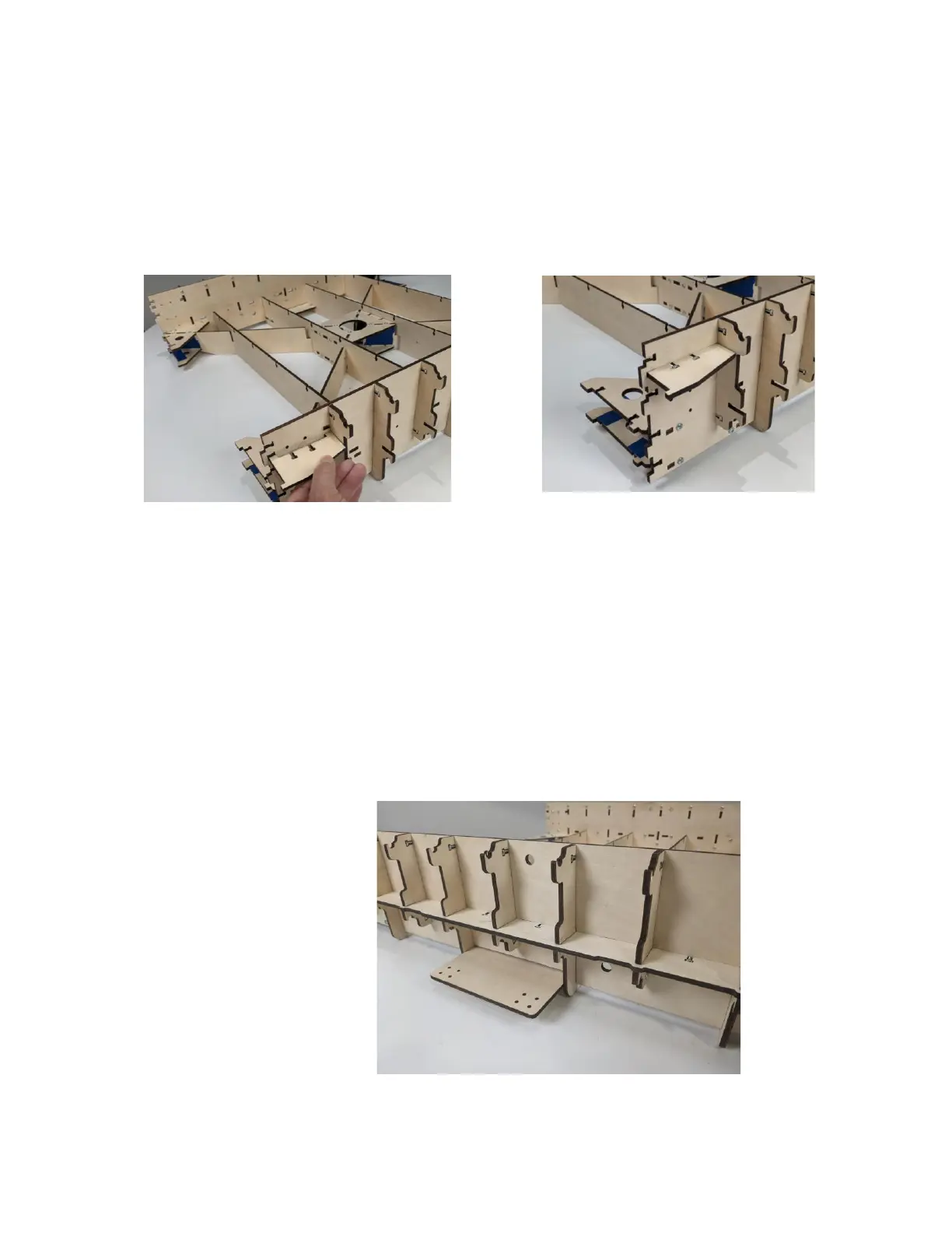
Step 10a Align the tabs of two of the Belt Supports
(QX11) in slots located at Rear of the X
Assembly and secure two M4 X 16Machine
Screws and Nuts for each, as shown.
Step 10b Align the slots of the Frame Side Brace (QX10)
with the slots in the Side Assembly. Insert the
tabs of the Frame Side Brace (QX10) into the
corresponding slots in the Side Assembly as
shown below. Secure with six M4 Machine
Screws and Nuts. Repeat to complete the
installation the Frame Side Brace on the
opposite side of the Assembly.