EasyManuals Logo

BobsCNC QUANTUM MAX User Manual

Default Icon
176 pages
To Next Page IconTo Next Page
To Previous Page IconTo Previous Page
Page #79 background imageLoading...
Page #79 background image
78
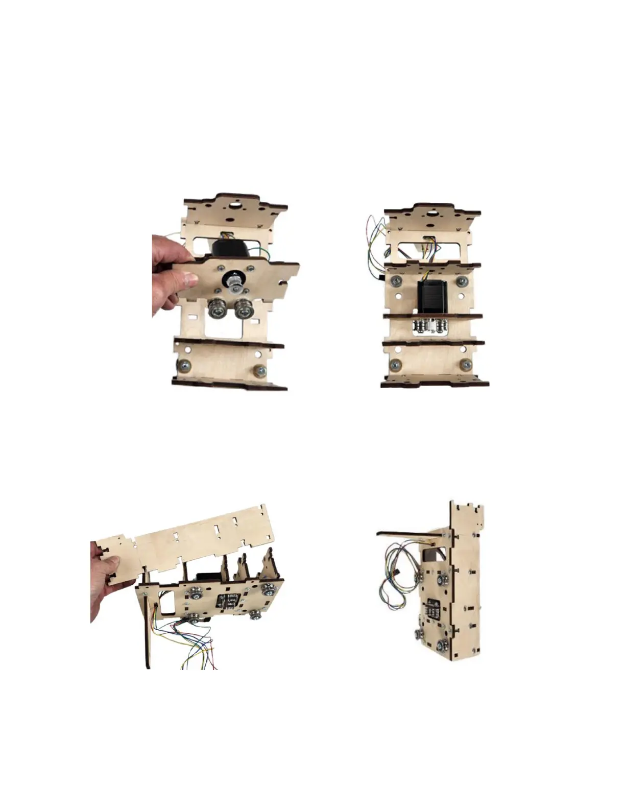
Step 2f With most of the wire threaded through the Y
Carriage Assembly, align the tabs of the Y
Stepper Motor Assembly with the
corresponding slots in the Carriage Frame
Assembly.
Step 2g Align the tabs and slots of the Carriage Side
Support (QY5) with the Y Carriage Frame
Assembly and secure with eight M4 x 16
Machine Screws and Nuts.
Repeat to attach the other Carriage Side Support.

Questions and Answers:

Question and Answer IconNeed help?

Do you have a question about the BobsCNC QUANTUM MAX and is the answer not in the manual?

BobsCNC QUANTUM MAX Specifications

General IconGeneral
BrandBobsCNC
ModelQUANTUM MAX
CategoryControl Systems
LanguageEnglish

Related product manuals