EasyManuals Logo

BobsCNC QUANTUM MAX User Manual

Default Icon
176 pages
To Next Page IconTo Next Page
To Previous Page IconTo Previous Page
Page #80 background imageLoading...
Page #80 background image
79
Step 2h Attach the Z Rail Stop (QY6) to the
bottom of the Y Carriage Frame Assembly and
secure with two M4 x 20 Machine Screws (H98) and
M4 Lock Nuts (H47).
Step 3 Attaching the Z Frame Assembly to the Y Carriage
Frame Assembly
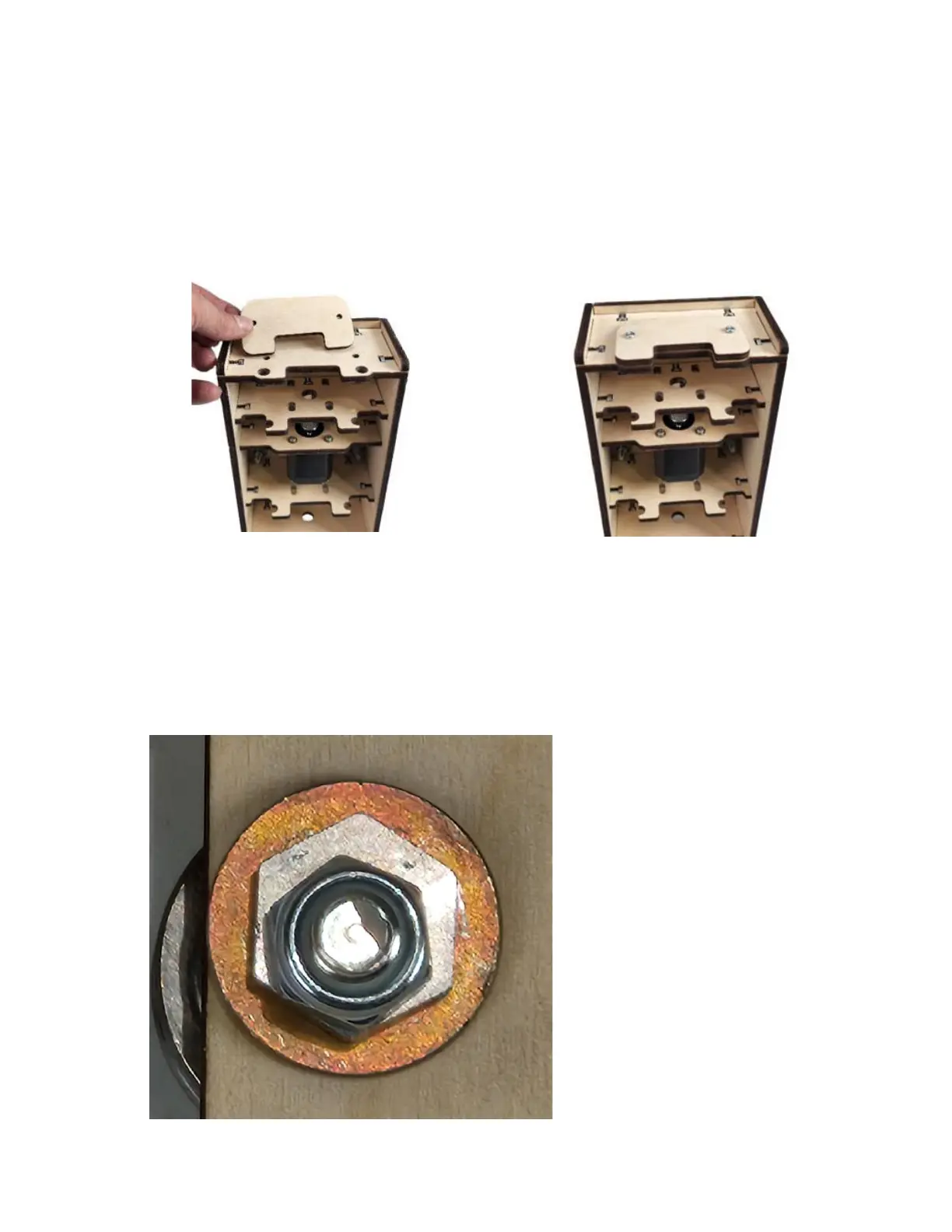
This closeup view shows the
Locknut tightened against the
Eccentic Spacer. Note the
space between the faces of the
locknut and those of the
Eccentric Spacer. This will
indicate the position of the
SG20U Bearing and the Rail.

Questions and Answers:

Question and Answer IconNeed help?

Do you have a question about the BobsCNC QUANTUM MAX and is the answer not in the manual?

BobsCNC QUANTUM MAX Specifications

General IconGeneral
BrandBobsCNC
ModelQUANTUM MAX
CategoryControl Systems
LanguageEnglish

Related product manuals