The signal frequency at the selected repetition frequency input can be scaled via the
parameter Divider 497
. The parameter figure is comparable with the division marks
of a speed sensor per rotation of the drive mechanism. The frequency limit of
the
parameterized digital input is to be taken into account for the frequency of the input
signal.
No. Description Min. Max. Fact. sett.
497 Divider 1 8192 1024
The reference value specification within the different functions enables the use of the
repetition frequency signal as a percentage figure. A signal frequency of 100 Hz at the
repetition fre
quency input corresponds to 100%, 1 Hz corresponds to 1%. The para
m-
eter Divider 497 is to be used in a way comparable with the speed sensor simulation.
Via parameters Offset 652 and Amplification 653, the PWM input signal can be
adjusted for the application.
No. Description Min. Max. Fact. sett.
652 Offset -100.00% 100.00% 0.00%
[ ]
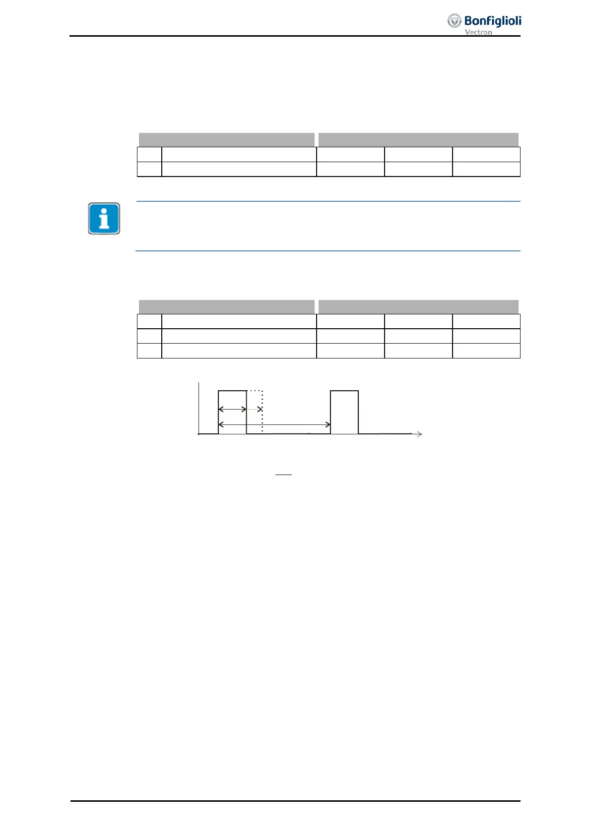
×+=− 653652 % ionAmplificat
T
T
ges
on
Offset
ValuePWM
Set the reference value via one the following modes.
− For reference frequency values:
Reference Frequency Source 475 = “32 - Rep. Frequency Input (F3)”. The
PWM-value is related to
Maximum Frequency 419.
− For reference percentage values:
Reference Percentage Source 476 = “32 - Rep. Frequency Input (F3)”. The
PWM-value is related to Maximum Reference Percentage 519.
Parameter PWM-Input 258 shows the actual value of the PWM input.
06/13 Operating Instructions ACU 171
 Loading...
