14 en | Installation Extension board with 16-input 16-output
2024-01 | V02 |
Installation manual
Bosch Security Systems B.V.
4.5 Cabling
Notice!
Risk of malfunction
When connecting the extension to the controllers, twisted pair shielded cables should be
used. The other cables used are not susceptible to electrical interference. However, you
should avoid laying cables close to heavy-duty switch cables and equipment. If this is
unavoidable, cross the cables at right angles every 1 to 2 m (3 to 6 ft) to reduce
interference.
4.5.1 Choosing the appropriate cable to avoid high power drops
With the calculation below you can find out which cable type must be used. If you connect
the power supply and the extension with the delivered cable set from the enclosure, the
calculation is not necessary.
For distances below 25m (75ft) use AWG18 conductors (1mm²). For longer distances,
install an additional power supply close to the extension.
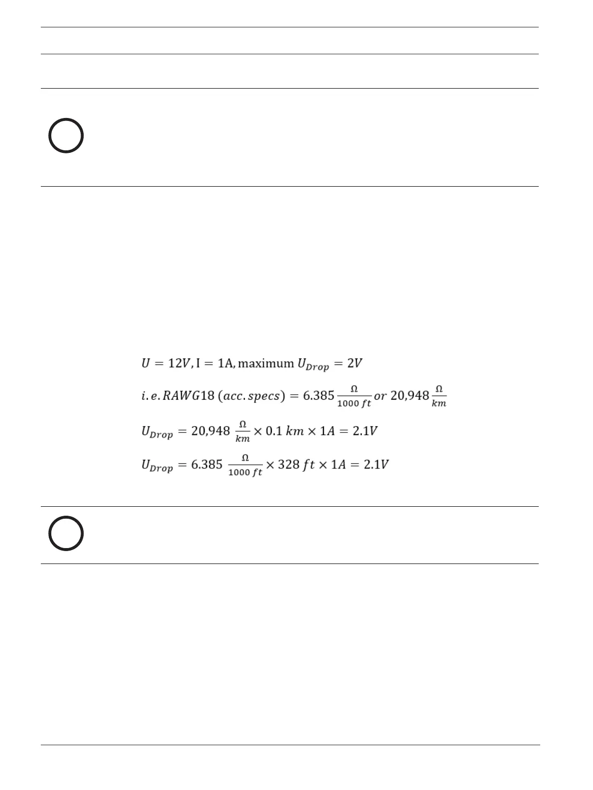
Please, calculate the voltage drop by checking the conductor specifications for
characteristic resistance values. The voltage drop shall not exceed 2V.
Example:
Length = 100 m/328 ft
Critical condition! Install the power supply closer to the extension.
Notice!
These specifications apply to power supply, relay outputs, and extension interface.
Regarding inputs, specific voltage-drop values need to be taken into account. Refer to
chapter Connecting analog input devices, page 24.