22 en | Installation Extension board with 16-input 16-output
2024-01 | V02 |
Installation manual
Bosch Security Systems B.V.
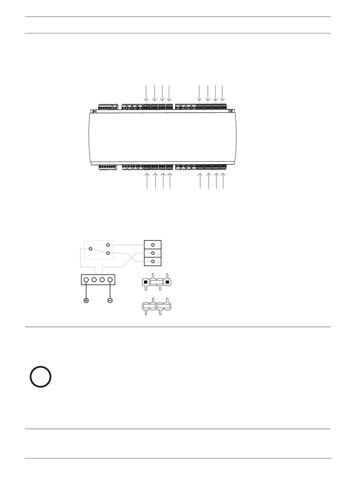
4.9 Connecting relay outputs
The AMC2-16IOE has 16 relay outputs. The outputs will be connected to the 3-pin pluggable
screw connectors S6, S7, S8, S9, S14, S15, S16, S17, S24, S25, S26, S27, S32, S33, S34
and S35 - refer to chapter Connecting diagrams, page 37.
Figure4.12: Location of the relay output connectors
By default, the relay outputs are connected as floating contacts (E1). However, it is possible
to connect the internal voltage 12/24 V to each relay output (E2) to control external
consumers.
Figure4.13: Relay mode settings
Notice!
Risk of damage to equipment
To prevent damage to the relays, note these specifications:
- The maximum switching current is 1.25 A.
- The maximum switching voltage is 30 VDC.
- Only OHM resistive load can be connected to the relay.
- Inductive loads have to be short circuited using recovery diodes. The diodes (1N4004) are
supplied with every extension.
- If you need higher voltage or current for special applications, or electric door holding
magnets, you have to use coupling relays (e.g. Wieland flare move) on the outputs.
- Note that the coupling relays must be selected according to the supply voltage (12 V, 24
V) of the controller.