24 en | Installation Extension board with 16-input 16-output
2024-01 | V02 |
Installation manual
Bosch Security Systems B.V.
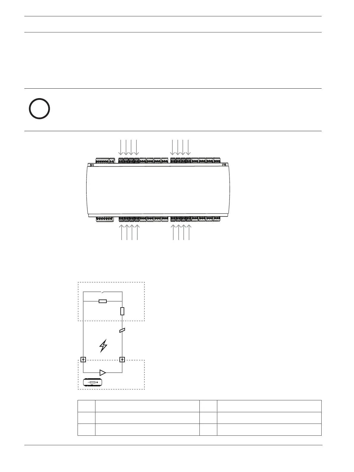
4.10 Connecting analog input devices
The AMC2-16IOE has 16 analog inputs. The inputs will be connected to the 2-pin pluggable
screw connectors: S2, S3, S4, S5, S10, S11, S12, S13, S20, S21, S22, S23, S28, S29, S30
and S31.
For more information on these connections, refer to Connecting diagrams, page 37.
Notice!
Risk of damage to equipment
Do not connect external power supply to the extension inputs.
When connecting a relay output directly to an extension input use potential-free contact -
refer to Connecting relay outputs, page 22.
Figure4.16: Location of the analog input connectors
The controller can also detect the wiring conditions ‘short circuit’ and ‘broken’, and hence
trigger an alarm if the appropriate devices are connected.
Figure4.17: Circuit diagram
1 AMC2 analog input 2 Monitoring / door contact
3 Resistor parallel (R
P
) 4 Resistor serial (R
S
)
5 Broken wire 6 Short circuit