Extension board with 16-input 16-output Appendices | en 37
Bosch Security Systems B.V.
Installation manual
2024-01 | V02 |
10 Appendices
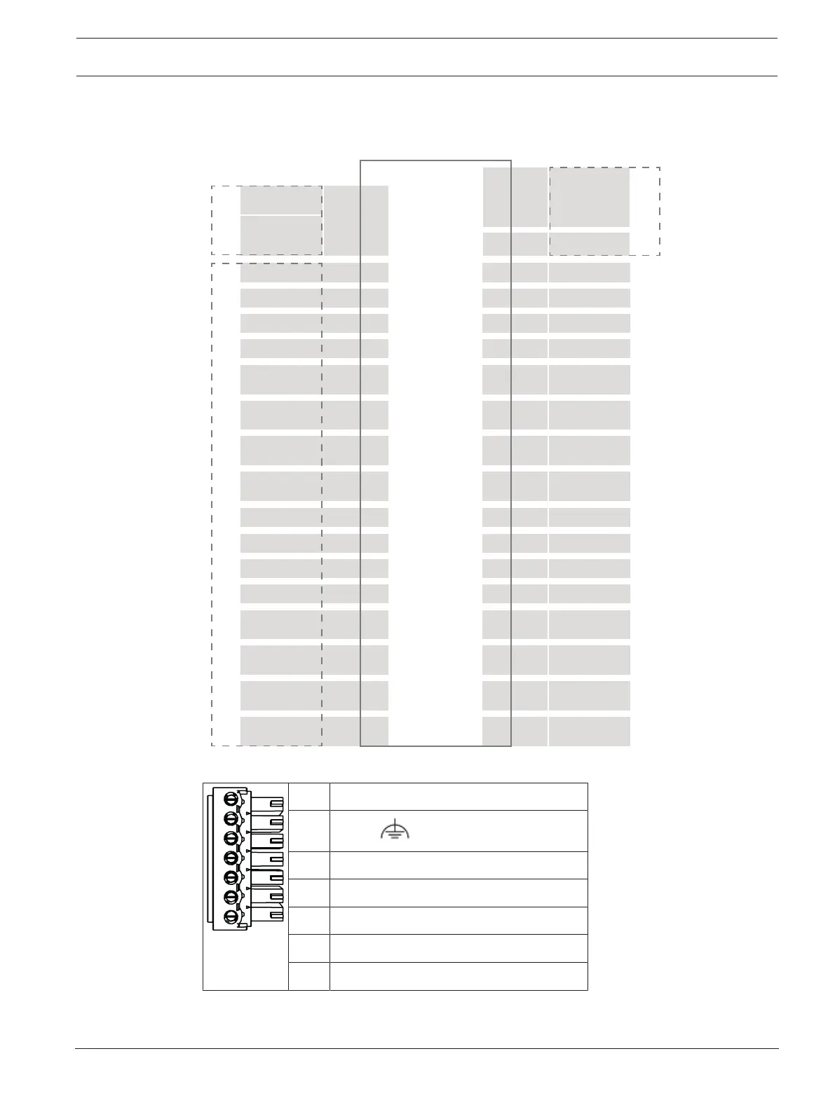
10.1 Connecting diagrams
Analog Input 11
Analog Input 12
Analog Input 9
1
2
Analog Input 10
Relay Output 9
1
2
3
Relay Output 102
Relay Output 11
2
Relay Output 122
Analog Input 15
Analog Input 16
Analog Input 13
Analog Input 14
Relay Output 13
2
Relay Output 14
2
Relay Output 15
2
S22
S23
S20
S21
S24
S25
S26
S27
S30
S31
S28
S29
S32
S33
S34
S35
Relay Output 16
2
AMC2 16IOE
Additional
Power Supply
Power Supply
UPS
S1
S18
S19 Tamper Contact
RS485-Bus
S4
Analog Input 3
1
2
S5
Analog Input 4
1
2
S2
Analog Input 1
1
2
S3Analog Input 2
1
2
S6Relay Output 1
1
2
3
S7
Relay Output 2
1
2
3
S8Relay Output 3
1
2
3
S9
Relay Output 4
1
2
3
S12
Analog Input 7
1
2
S13Analog Input 8
1
2
S10
Analog Input 5
1
2
S11
Analog Input 6
1
2
S14Relay Output 5
1
2
3
S15
Relay Output 6
1
2
3
S16Relay Output 7
1
2
3
S17
Relay Output 8
1
2
3
1
2
3
4
5
6
7
1
2
6
5
4
3
2
1
1
2
1
2
1
2
1
2
1
2
1
2
1
2
1
3
1
3
1
3
1
3
1
3
1
3
1
3
Figure10.1: Connector blocks of the AMC2-16IOE
1 Power supply, DC positive (10V - 30V)
2
Shield
3 Power supply (0V)
4 UPS (power good signal) - AC
5 UPS (power good signal) - Battery
6 UPS (power good signal) - DC
7 UPS (power good signal) - Common
Table10.3: Power supply