8 en | Introduction Extension board with 16-input 16-output
2024-01 | V02 |
Installation manual
Bosch Security Systems B.V.
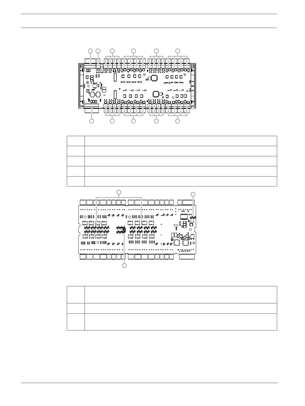
3.2 Product overview
Figure3.2: Overview - Interfaces
1 RS-485 extension module bus
2 External tamper contact
3 Connectors for analog inputs
4 Connectors for relay outputs
5 Connector for power supply
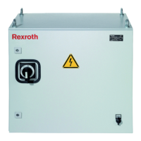
Figure3.3: Jumpers at the bottom side
6 Jumper for setting either a free voltage from the relay output or a looped-in voltage
from the internal power supply of the controller.
7 DIL switch for setting the board address.
8 Jumper: Equalization of potential between different systems and earth ground
(shield) for the extension module bus.