AVENAR panel AVENAR panel series | en 13
Bosch Sicherheitssysteme GmbH
System manual
2022-07 | 5.0 | F.01U.378.910
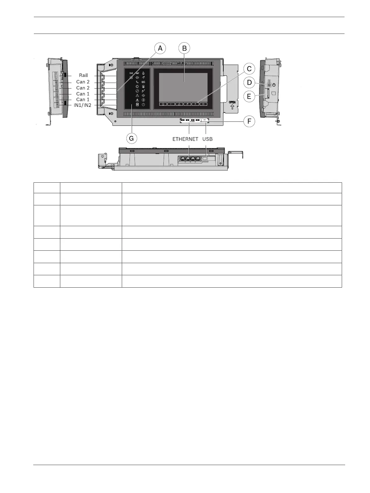
Figure2.2: Overview of panel controller
Pos. Designation Function
A Interfaces Panel networking and inputs for internal device monitoring
B Touchscreen Operating the networked system through virtual buttons and variable display
windows
C 6 fixed buttons Standard entries
D Power button Shutdown and restart of the device
E Memory card slot Memory card reader for maintenance services
F Ethernet ports Panel networking and interface to various systems
G 18 LEDs Indicating the operating status
Networking
A panel controller with premium license can be networked with up to 32panel controllers,
remote keypads and OPC servers.
Panels and keypads display all messages, or you can form a group of panels and keypads.
Within one group, only messages of this group are displayed.
Alarm indication
All messages are shown on the display with a bright color. The displayed messages contain the
following information:
– Message type
– Type of the triggering element
– Description of the exact location of the triggering element
– Logical zone and sub-address of the triggering element
At any time, the operator can request a status overview for each evacuation zone and each
output connected to the fire protection equipment.
18Icon LEDs give continuous information about the operating status of the panel or the
system. A red icon LED shows an alarm. A blinking yellow icon LED shows a fault. A steady
yellow icon LED shows a disabled function. A green icon LED shows proper operation.
Two status LEDs, one red and one yellow, are programmable. The red one shows a self-
defined alarm. The yellow one shows a self-defined fault or deactivation.